Servo press with elbow lever drive

a technology of lever drive and servo press, which is applied in the direction of presses, presses, manufacturing tools, etc., can solve the problem of inability to obtain accurate control of the plunger movemen

Inactive Publication Date: 2006-07-20
SCHULER PRESSEN GMBH & CO KG
View PDF6 Cites 30 Cited by
  • Summary
  • Abstract
  • Description
  • Claims
  • Application Information

AI Technical Summary

Benefits of technology

[0015] While the auxiliary drives may simply include transmissions with constant transmission ratios (such as the pull-type drives and gear rack drives etc. . . . mentioned above) also nonlinear drives may be used, that is drives whose transmission ratios are not constant. The auxiliary drive may be itself in the form of an elbow lever drive. Also the drive sources of the auxiliary drive which are preferably electromagnetic drives may use different principles. They may be for example pressure or position-controlled hydraulic drives or pneumatic drives. These drives are controllable at least to the extent that the direction of the force applied by them to the plunger can be reversed. In the most simple case, such an auxiliary drive may be a hydraulic cylinder to which a compressible or noncompressible fluid is supplied in order to move the plunger in a controlled manner against a force such as the plunger weight or another pre-tensioning structure. Such a fluid drive may be sufficient to move the plunger in a reasonably controlled manner into the indifference range of the elbow lever drive and if necessary through this range. If the main drive of the plunger formed by the servomotor as well as the auxiliary drive are both position-controlled drives, it is expedient if at least the auxiliary drive includes an elastic element by which it is connected to the plunger or to the stationary support structure. Alternatively, the auxiliary drive may itself have elastic characteristics. In this way, it is prevented that the servomotor and the auxiliary matter act rigidly against each other and are locked thereby.

Problems solved by technology

This means that, with a force effective on the hinge point of the two elbow lever arms, an accurately controlled movement of the plunger cannot be obtained.

Method used


Image

  • Servo press with elbow lever drive
  • Servo press with elbow lever drive
  • Servo press with elbow lever drive

Examples


Embodiment Construction

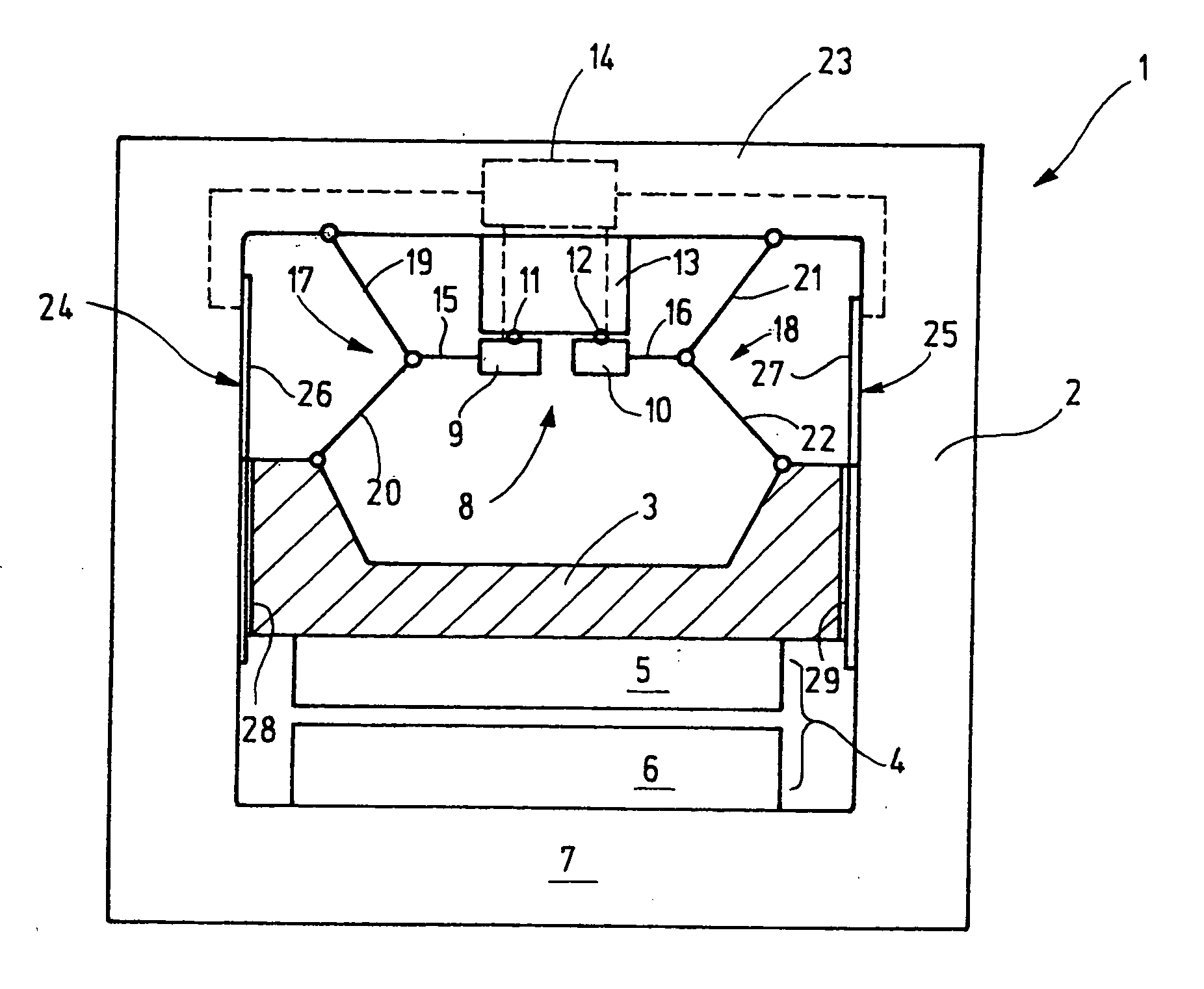
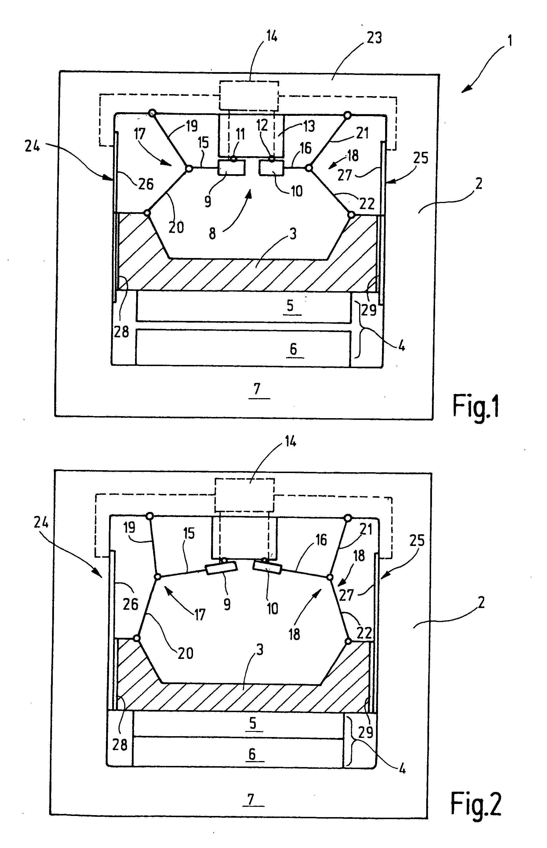
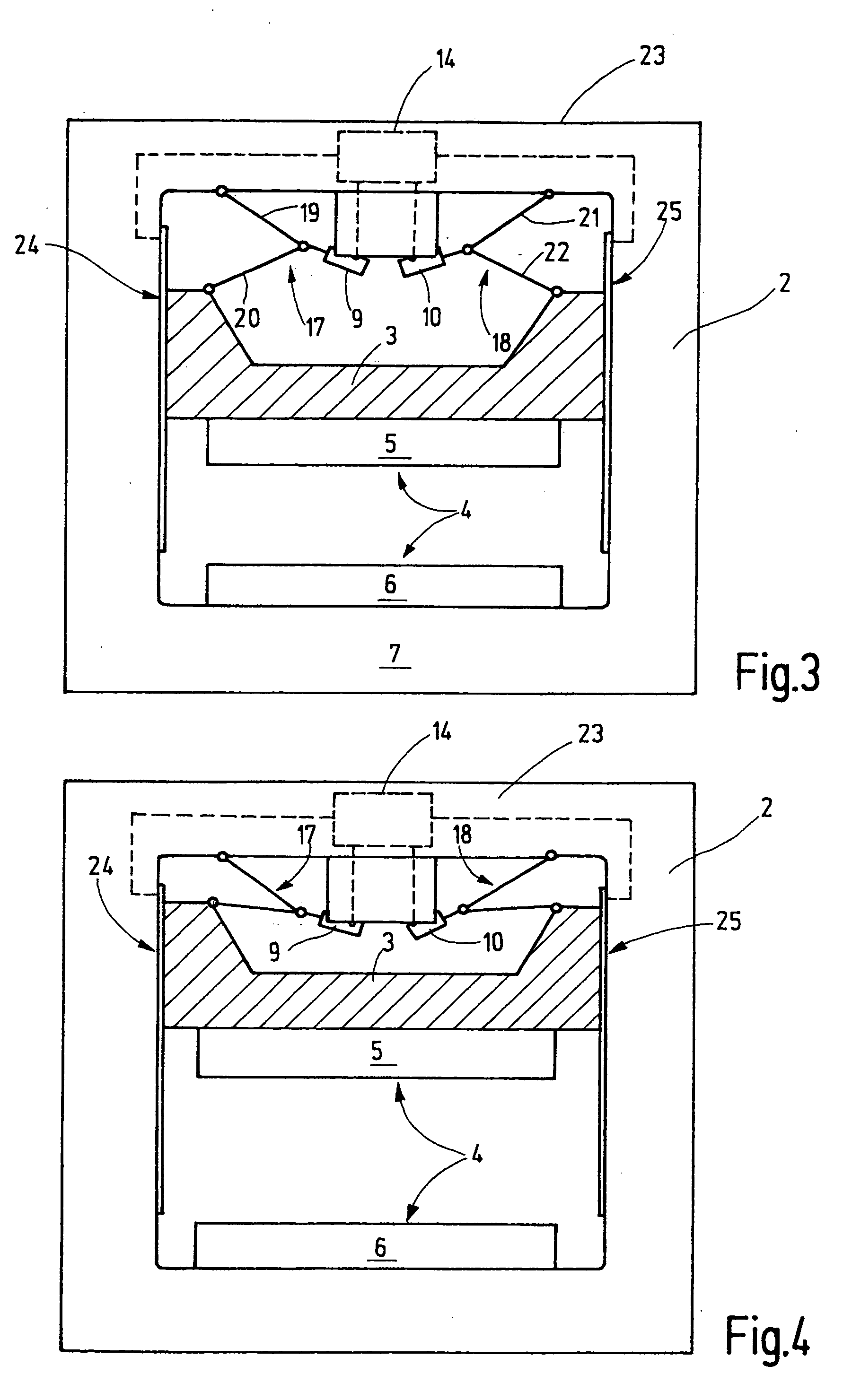
[0024]FIG. 1 shows schematically a press 1 which comprises a press frame 2 and a plunger 3 preferably linearly movably supported therein. For guiding the plunger, there is a linear guide structure which is not shown. At the front end of the plunger 3, a top die tool 5 is attached to the plunger 3, which is part of a die 4. A lower die tool 6 is disposed on a press table 7. The deforming-tool may be a large tool for deforming sheet metal. The press 1 may be an individual unit or part of a large component stage or stepping press arrangement. Such a large component stage press arrangement may include a common press frame, in which several plungers of the type shown in FIG. 11 are movably supported. A transfer structure moves the metal sheets from press stage to press stage. Several presses of the type shown in FIG. 1 may also be set up independently of one another and interconnected by a transfer arrangement by which the metal sheets are transferred. However, the press 1 may also be a ...


PUM


Abstract

In a press comprising a frame structure, a plunger movably supported by the frame structure, at least one servomotor for driving the plunger and an elbow lever drive connected to the servomotor and the plunger for actuating the plunger, at least one auxiliary drive is connected to the plunger for operating the plunger in stroke ranges where the elbow lever drive is ineffective for controllably moving the plunger.

Description

BACKGROUND OF THE INVENTION [0001] The invention resides in a servo press with an elbow lever drive and a plunger which is movable back and forth in a predetermined direction and a servomotor for operating the elbow lever drive. [0002] For deforming sheet metal parts, often a so-called large part stepping press is used. Such a press includes several plungers each of which is driven by eccenters via a connecting rod and the eccenters are all rotated by a common main shaft. The individual plungers are operated in phase or with a certain phase shift. The back and forth movement of the individual plunges is derived from an essentially uniform rotational movement of the main shaft. [0003] For controlling the plunger stroke, a so-called stroke adjustment may be provided by which the effective eccentricity of the respective eccenter is adjustable. Furthermore, in place of the simple connecting rod connection between the eccenter and the plunger a lever drive may be provided which changes t...

Claims


Application Information

Patent Timeline
Patent Type & Authority Applications(United States)
IPC IPC(8): B30B1/10
CPCB30B1/10
Inventor HOFELE, HANSLAUKE, ANDREAS
Owner SCHULER PRESSEN GMBH & CO KG
Why Eureka
Try Eureka