
System and method for producing fluids from a subterranean formation

a technology of subterranean formations and fluids, applied in drinking water installations, directional drilling, borehole/well accessories, etc., can solve the problems of limited fracture half-lengths, ineffective and inefficient fracture stimulation methodologies, and many zones left unstimulated

Active Publication Date: 2006-07-20
HALLIBURTON ENERGY SERVICES INC +1
View PDF27 Cites 50 Cited by
  • Summary
  • Abstract
  • Description
  • Claims
  • Application Information

AI Technical Summary

Benefits of technology

This patent describes a system that can produce fluids from underground reservoirs through a network of pipes and wells. There are also pumps to help move the fluids out of the ground. Overall, this technology allows for efficient drilling and extraction of oil and gas from deep beneath the earth's surface.

Problems solved by technology

The technical problem addressed in this patent text relates to improving the efficiency of exploring oil fields that have multiple layers of formations containing various amounts of oil and gas. Existing procedures involve considerable expense and risk, particularly when trying to determine whether certain zones offer economic benefits. Additionally, previous solutions have resulted in long delays and difficulty accessing remote locations. This new invention provides an improved system and method for producing fluids from subterranean formations more efficiently than previously known methods.

Method used


Image

  • System and method for producing fluids from a subterranean formation
  • System and method for producing fluids from a subterranean formation
  • System and method for producing fluids from a subterranean formation

Examples


Embodiment Construction

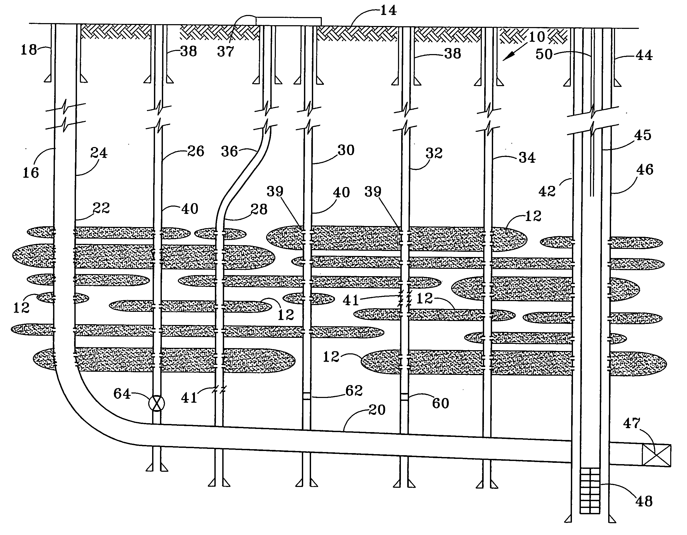
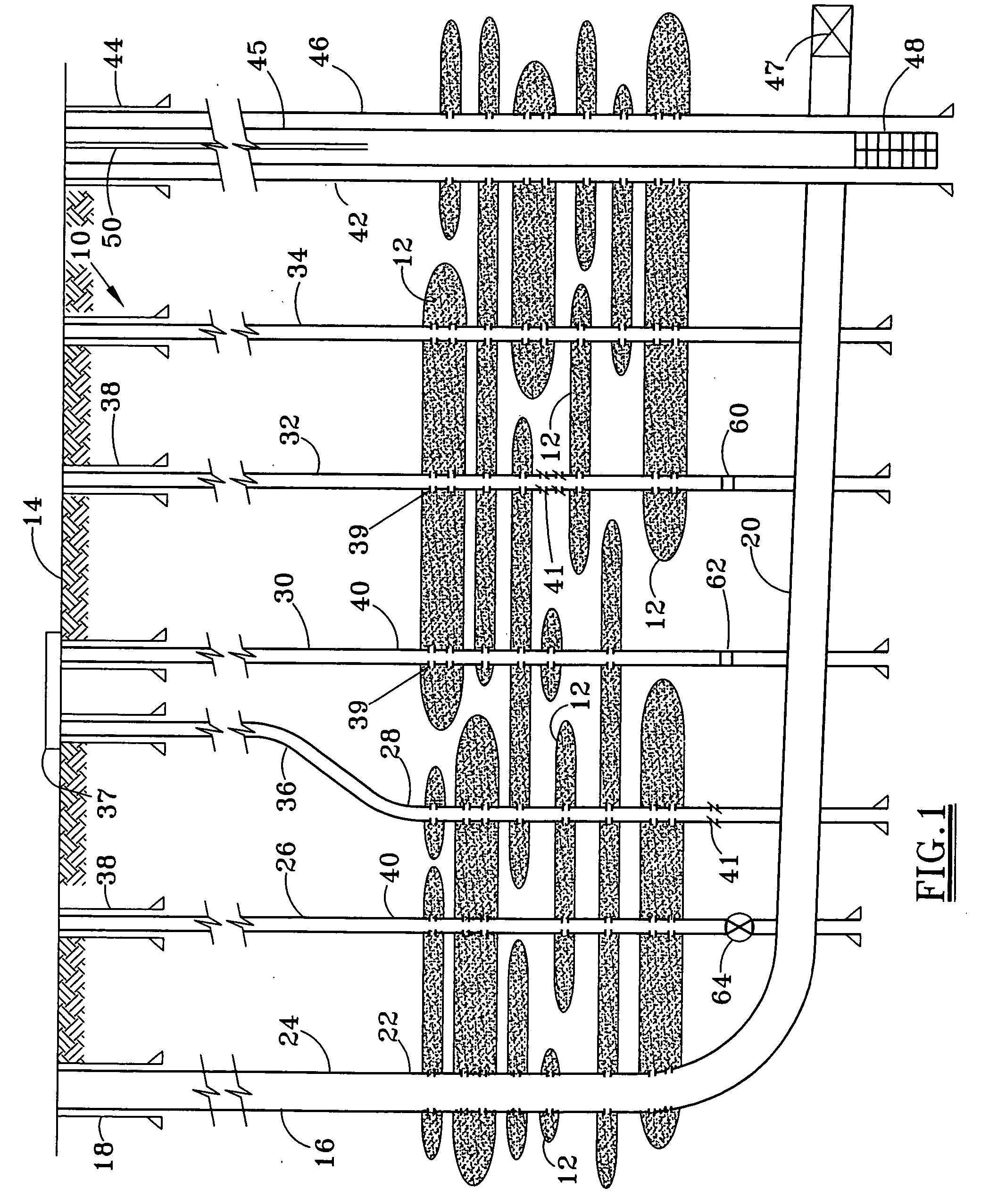
[0033] The present invention may be used in the recovery of hydrocarbons in oilfield development applications whereby the hydrocarbons are dispersed in stacked sequence of highly compartmentalized reservoirs within a relatively thick gross interval of permeable sands and impermeable, non-productive shales. In many cases, the desired hydrocarbon production is crude oil from relatively small sand lenses or reservoir compartments having poor reservoir continuity and heterogeneous rock properties, and which commonly require fracture stimulation. Due to the relatively small size of each sand lense or reservoir compartment, commingling of many separate zones into a single completion achieves efficient and economic exploitation.

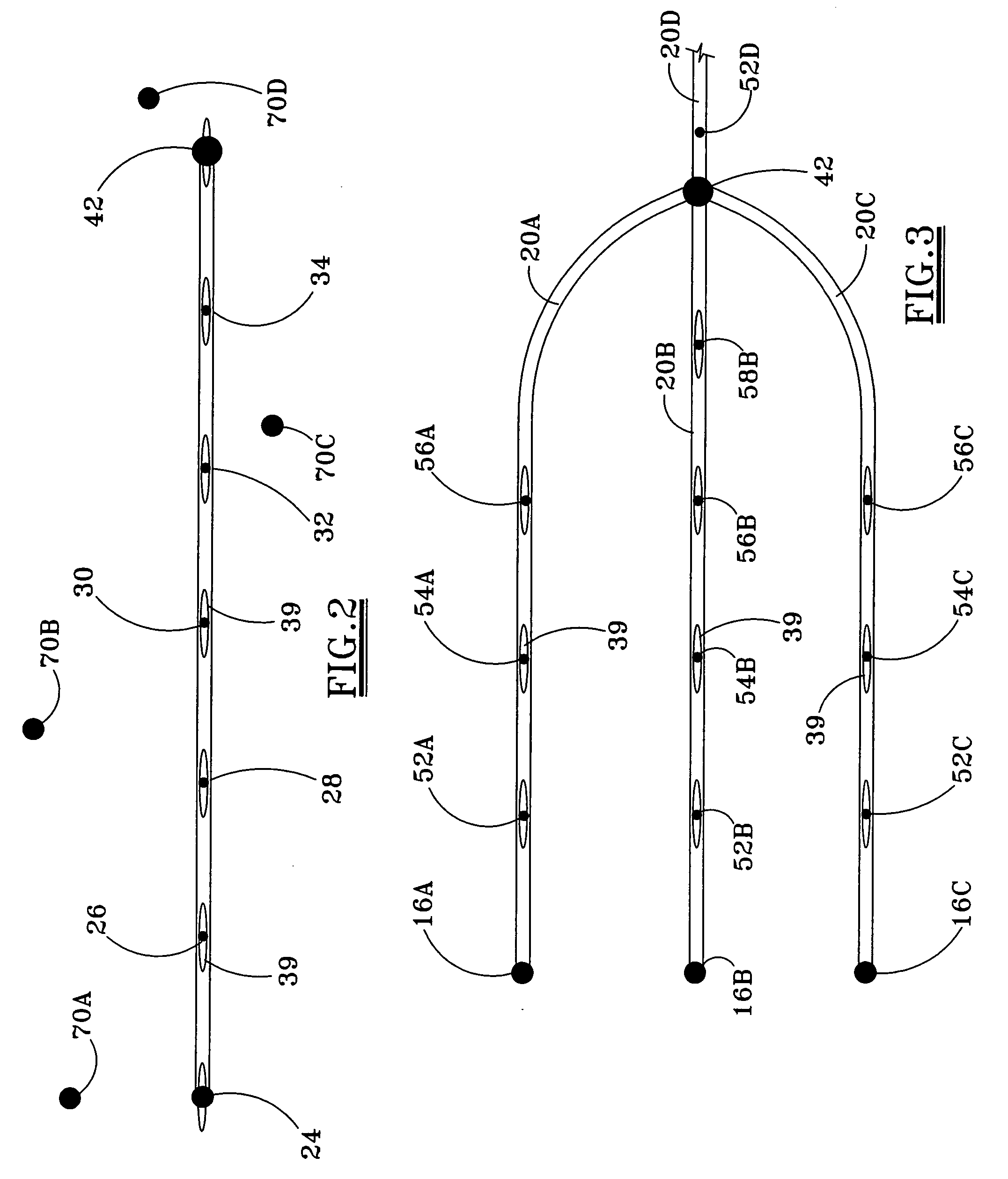
[0034] In one embodiment, the present invention enables a large number of relatively thin reservoirs to be efficiently completed, optionally with frac stimulation, from a subsurface flow line and multiple drainage wells. The subsurface flow line is in fluid communi...


PUM


Abstract

The system of subterranean wells includes a subsurface flow line 20 having at least a portion within or underlining one or more subterranean formations 12. One or more drainage wells 26, 28, 30, 32, and 34 each extend from the surface and intercept at least one of the subterranean formations at a respective interception location. A lower portion of each drainage well is in fluid communication with the subsurface flow line. A recovery well 42 extends from the surface and is also in fluid communication with the subsurface flow line, so that fluids entering the drainage well flow into the subsurface flow line and then into the recovery well.

Description


Claims


Application Information

Patent Timeline
Owner HALLIBURTON ENERGY SERVICES INC
Learn More