Wagering game with player-determined symbol function

a technology of player-determined symbols and wagering games, applied in the field of wagering terminals, can solve the problems of players feeling dissatisfied when they lose, the jackpot progressively increasing at a much faster rate, and the excitement of players

a technology of player-determined symbols and wagering games, applied in the field of wagering terminals, can solve the problems of players feeling dissatisfied when they lose, the jackpot progressively increasing at a much faster rate, and the excitement of players

US20060160613A1Active Publication Date: 2006-07-20LNW GAMING INC

Image

  • Wagering game with player-determined symbol function
  • Wagering game with player-determined symbol function
  • Wagering game with player-determined symbol function

Examples


Embodiment Construction

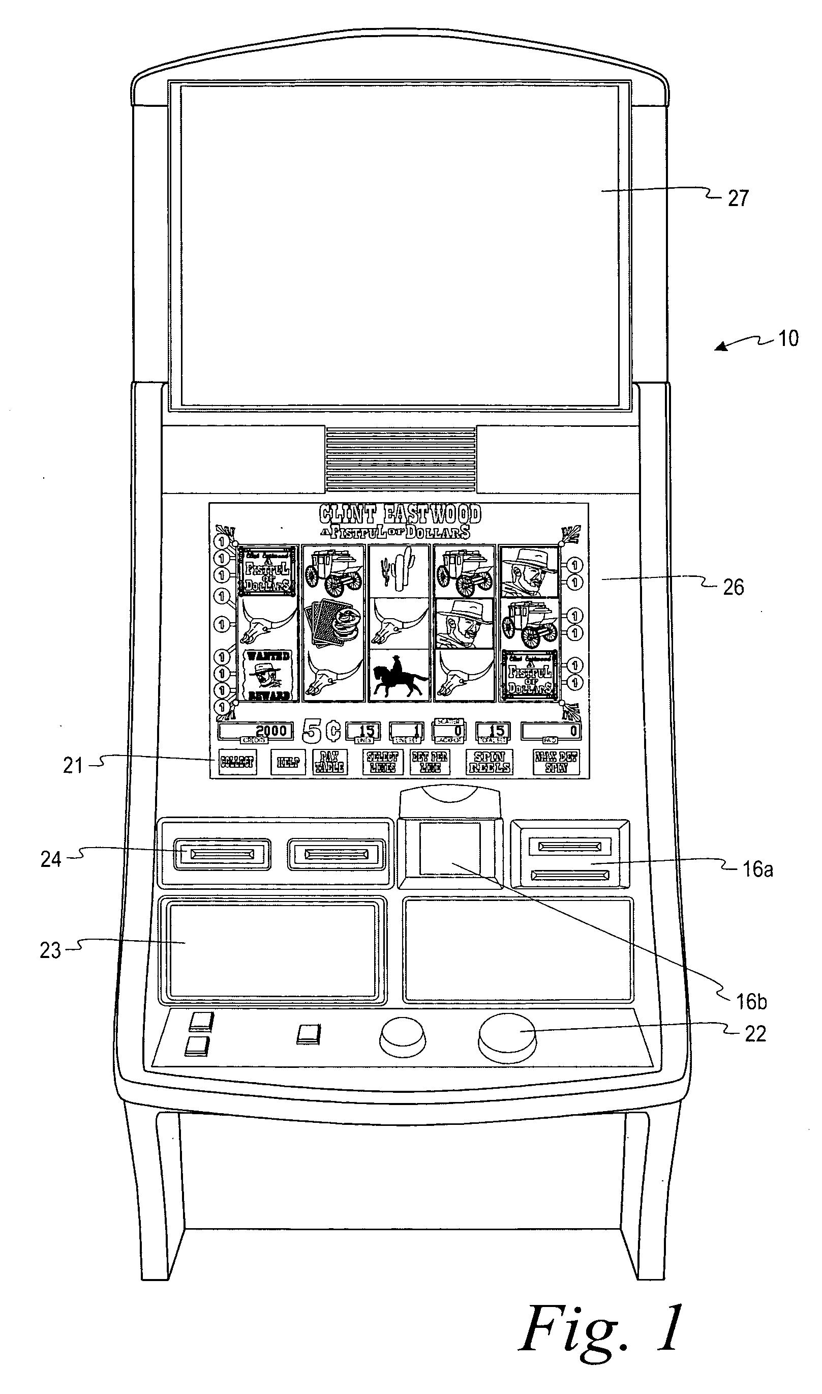
[0024]FIG. 1 shows a perspective view of a typical gaming terminal 10 used by gaming establishments, such as casinos. With regard to the present invention, the gaming terminal 10 may be any type of gaming terminal and may have varying structures and methods of operation. For example, the gaming terminal 10 may be an electromechanical or electrical gaming terminal configured to play video slots or a video casino game, such as blackjack, slots, keno, poker, etc.

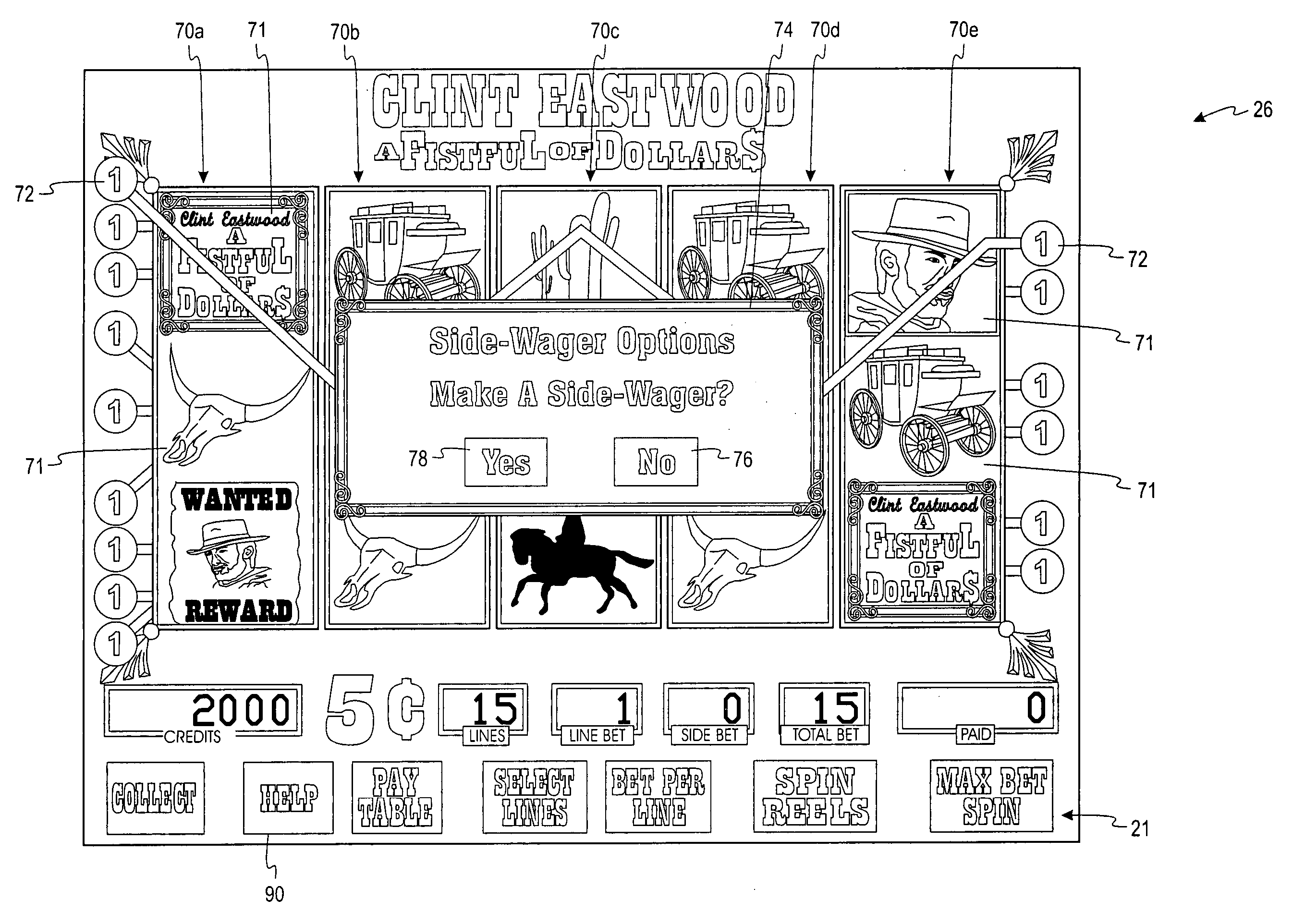
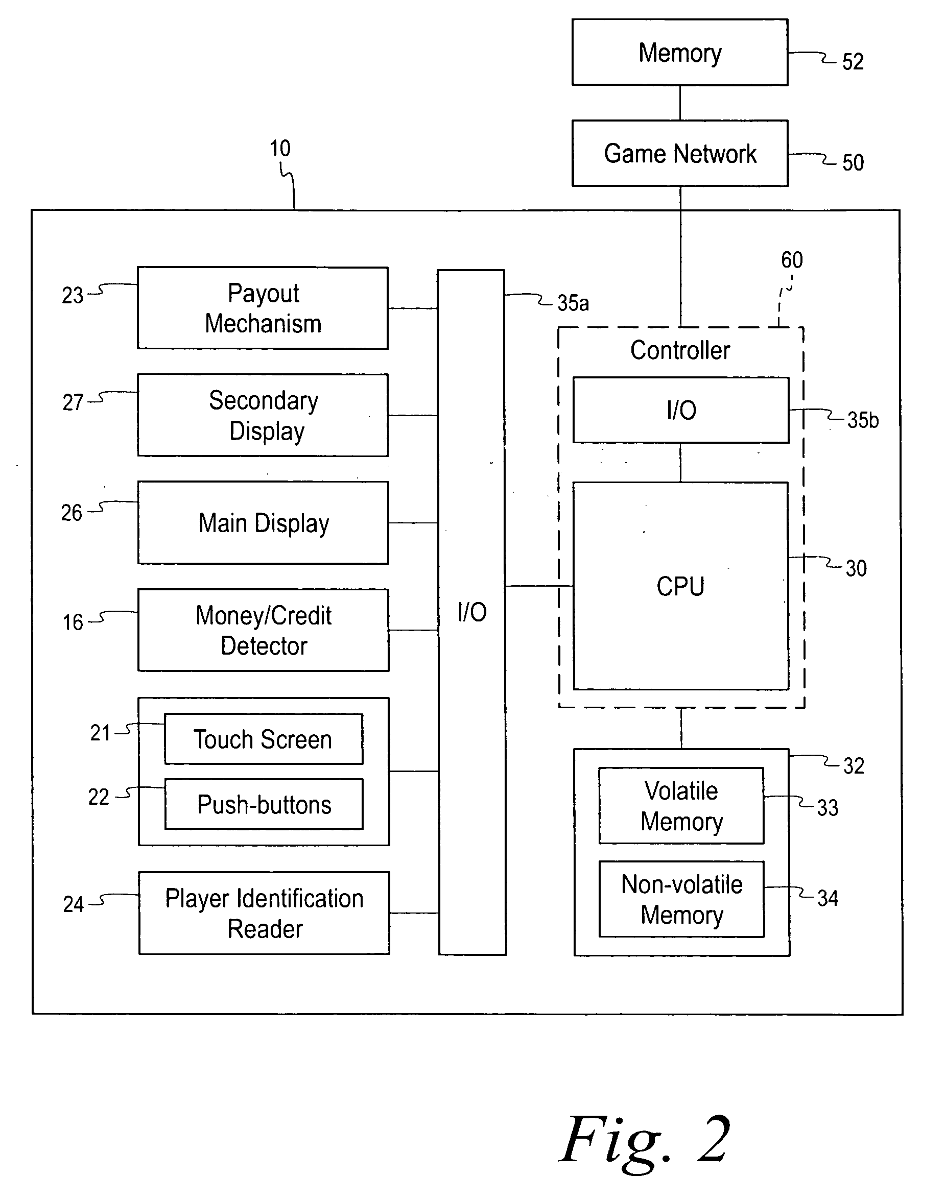
[0025] As shown, the gaming terminal 10 includes input devices, such as a wager acceptor 16 (shown as a card wager acceptor 16a and a cash wager accepter 16b), a touch screen 21, a push-button panel 22, and an information reader 24. For outputs, the gaming terminal 10 includes a payout mechanism 23, a main display 26 for displaying information about the basic wagering game, and a secondary display 27 that may display an electronic version of a pay table, and / or also possibly game-related information or other entertainment feat...


PUM


Abstract

A method for playing a wagering game. The method includes conducting a basic game having a randomly selected outcome. The randomly selected outcome is selected from a plurality of outcomes and is indicated by a plurality of symbols. Each of the plurality of symbols has a first function. A side-wager option is presented that allows a player to change a function of a certain one of the plurality of symbols to one of a plurality of second functions. In response to the player selecting the side-wager option, one of the plurality of second functions is selected. Also, the second function is attributed to the certain one of the plurality of symbols when the randomly selected outcome is indicated.

Description

CROSS-REFERENCE TO RELATED APPLICATIONS [0001] This application claims the benefit of priority of U.S. Provisional Patent Application No. 60 / 644,223, filed Jan. 14, 2005, which is hereby incorporated by reference in its entirety.FIELD OF THE INVENTION [0002] The present invention relates generally to gaming terminals for playing a wagering game and, more particularly, to a wagering game having a unique feature to allow a player to select a new function for a symbol. BACKGROUND OF THE INVENTION [0003] Gaming terminals, such as slot machines, video poker machines, and the like, have been a cornerstone of the gaming industry for several years. Generally, the popularity of such terminals with players is dependent on the likelihood (or perceived likelihood) of winning money at the terminal and the intrinsic entertainment value of the terminal relative to other available gaming options. Where the available gaming options include a number of competing terminals and the expectation of winni...

Claims


Application Information

Patent Timeline
20 Jul 2006
Publication
US20060160613A1
IPC
A63F9/24
CPC
G07F17/32; G07F17/3262
Inventors
HORNIK, JEREMY; JAFFE, JOEL R.