Hose clamp and spring liner

Active Publication Date: 2006-07-27
EPICOR IND
View PDF10 Cites 24 Cited by
  • Summary
  • Abstract
  • Description
  • Claims
  • Application Information

AI Technical Summary

Benefits of technology

[0006] Accordingly, it is an aspect of the present invention to provide an improved annular circumferentially corrugated spring liner for a hose clamp comprising: a central outwardly-directed circumferential ridge; an inwardly-directed circumferential ridge on each side of said central ridge; a

Problems solved by technology

Differing coefficients of thermal expansion of these components can result in thermally-induced reductions in clamping force, thus creating the potential for fluid or gas leakage.
In addition, changes in elasticity of the hose materials over time due to creep, c

Method used


Image

  • Hose clamp and spring liner
  • Hose clamp and spring liner

Examples


Embodiment Construction

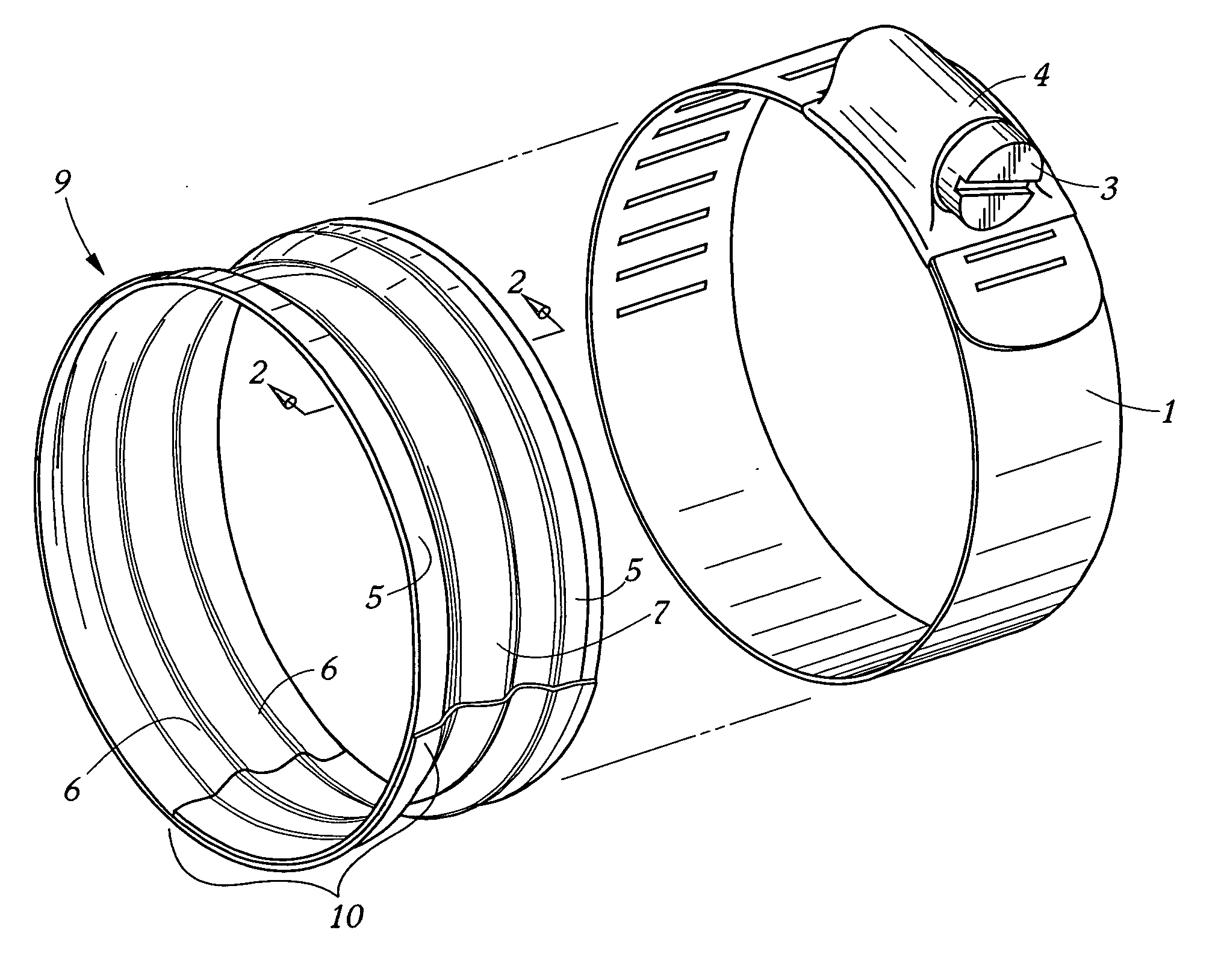
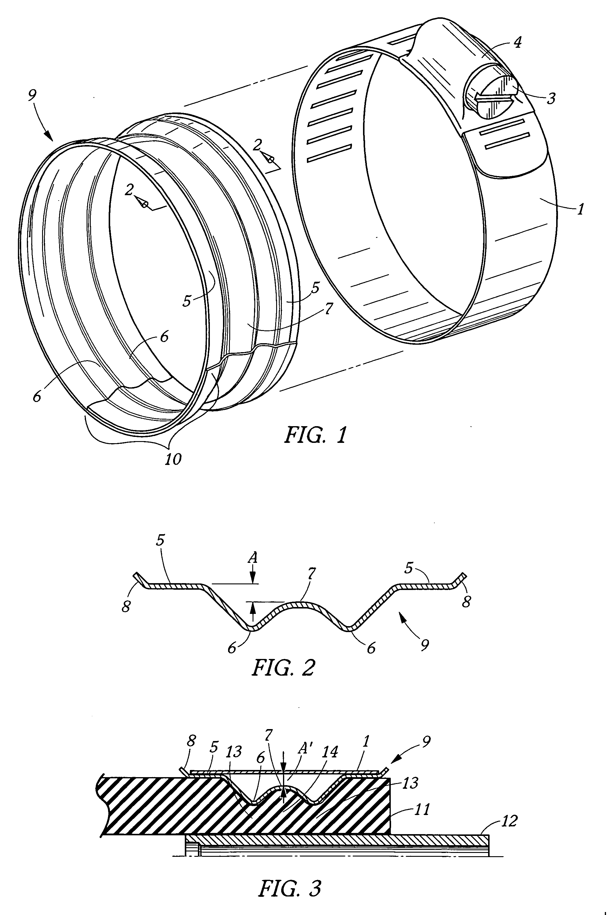
[0014] Referring to FIG. 1, a hose clamp is shown comprising an outer annular band 1, and a typical tensioning means 3, 4. FIG. 1 also shows in exploded view a wavy spring liner 9 in accordance with the present invention. Spring liner 9 is also shown in section in FIG. 2. Spring liner 9 is a circumferentially corrugated annular ring with overlapping ends 10. Spring liner 9 comprises two annular circumferential shoulders 5 near the edges of the liner, two radially inwardly-directed annular circumferential ridges 6 there between, and a radially outwardly-directed central annular circumferential ridge 7 located between the two inward ridges 6. FIG. 2 shows a radial height differential A between the two shoulders 5 and the central outwardly-directed ridge 7. When the liner 9 is inserted into the clamp band 1, the inner face of the band 1 will abut or seat on the shoulders 5, and a gap A will result between the ridge 7 and the inner face of the band 1.

[0015] The terms outward and inward...


PUM


Abstract

An improved hose clamp comprising: an annular band having an inner face, tensioning means, and an annular spring liner; said spring liner comprising: an outwardly-projecting circumferential ridge; an inwardly-projecting circumferential ridge on each side of said outwardly-projecting ridge; and a circumferential shoulder near an edge of said spring liner; wherein at least one said shoulder is adapted to abut said inner face.

Description

BACKGROUND OF THE INVENTION [0001] This invention relates to the field of hose clamp assemblies, more particularly, this invention relates to a spring liner that is associated with a hose clamp assembly, and allows the hose clamp to self-compensate for changes in elastic properties and diametric changes of the underlying hose and fittings. [0002] Hose clamps are commonly utilized to join together hoses and fittings or connectors (referred to hereinafter as fittings), for example, within the automotive industry. Hose clamps, hose and fittings respond to changes in ambient temperature and system temperatures based on the thermal properties of the aforementioned components. Differing coefficients of thermal expansion of these components can result in thermally-induced reductions in clamping force, thus creating the potential for fluid or gas leakage. In addition, changes in elasticity of the hose materials over time due to creep, compression set, or deterioration can also reduce the cl...

Claims


Application Information

Patent Timeline
IPC IPC(8): F16L33/00
CPCF16L33/08Y10T24/1457Y10T24/1441Y10T24/1412
Inventor BOWATER, BRUCE D.
Owner EPICOR IND
Why Eureka
Try Eureka