Liquid crystal display device and display equipment using the same

Inactive Publication Date: 2006-07-27
KYOCERA CORP
View PDF8 Cites 9 Cited by
  • Summary
  • Abstract
  • Description
  • Claims
  • Application Information

AI Technical Summary

Benefits of technology

[0028] In the liquid crystal display device having this configuration, a boundary line between the first color filter in the dark color and the second color filter in the light color is set on the light reflection region of the one pixel region, so that the second color filter having optical characteristics suitable for light reflection does not exist in the light transmission region. Consequently, an image quality in a transmission mode can be prevented from being reduced. In a reflection mode, a reflection factor is not substantially reduced. Therefore, it is possible to obtain an image quality excellent in white balance and having high color purity in the transmission mode, while having a high reflection factor and a high color purity in the reflection mode.
[0033] Also in these configurations, the second color filter suitable for the light reflection region does not exist in the light transmission region, so that the image quality in the transmission mode can be prevented from being reduced.

Problems solved by technology

In the reflection mode, outside light incident from a display surface passes a color filter two times, so that coloring (spectral transformation of light) by the color filter is increased, resulting in great loss of the outside light.
Therefore, brightness in the reflection mode cannot, in some cases, be sufficiently obtained.
On the other hand, as the disadvantage of the semi-transmission type liquid crystal display device, it is difficult to simultaneously satisfy the high color purity and the high reflection factor in the reflection mode.
Therefore, when a boundary between the first color filter and the second color filter occurs in the light transmission region, the boundary may deteriorate the image quality.

Method used


Image

  • Liquid crystal display device and display equipment using the same
  • Liquid crystal display device and display equipment using the same
  • Liquid crystal display device and display equipment using the same

Examples


example

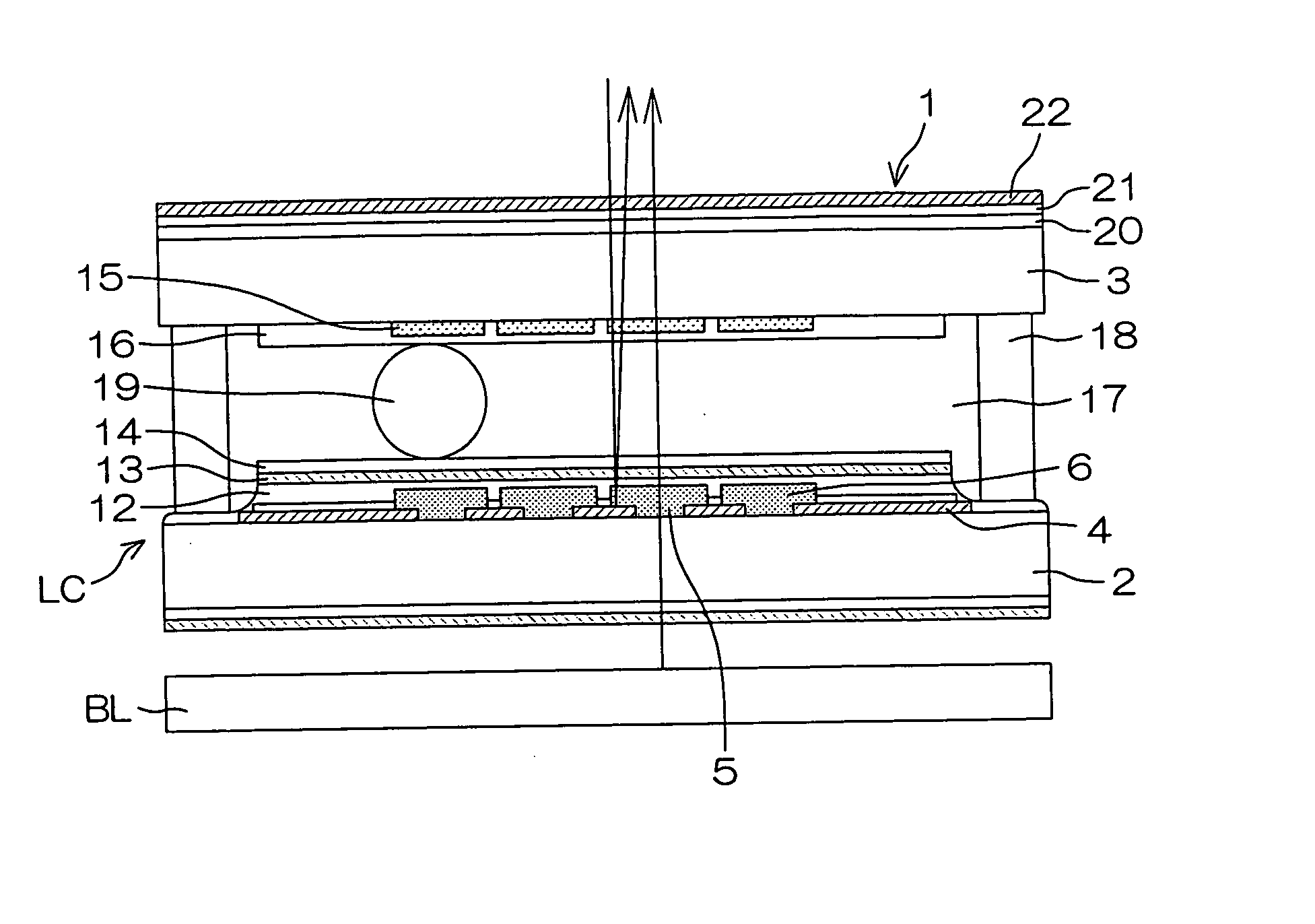
[0167] The inventors of the present invention produced a substrate 3 having color filters by steps shown in FIGS. 12(A) to 12(H) to manufacture a liquid crystal display device 1 having a configuration shown in FIG. 1, and measured the optical characteristics of the image quality thereof. As a comparative example, the inventors measured the optical characteristics of the image quality of a conventional configuration in which a hole was formed in a color filter having a high color

[0168]FIG. 15 is a graph showing results of measurement of respective wavelength spectra of the first color filter 9 and the second color filter 10 in the present embodiment. R1 represents the light transmission factor of the first color filter in red 9, and R2 represents the light transmission factor of the second color filter in red 10. G1 represents the light transmission factor of the first color filter in green 9, G2 represents the light transmission factor of the second color filter in green 10, B1 rep...


PUM


Abstract

A reflectable metal film having a light transmission hole 5 is formed on an inner surface of a transparent substrate 2, and a light transmission region 7 and a light reflection region 8 are arranged within each of pixel regions on the inner surface of the transparent substrate 2. A first color filter 9 and a second color filter 10 of a similar color that differs in tone are formed in each of the pixel regions. A boundary 11 between the first color filter 9 and the second color filter 10 in each of the pixel regions is positioned in the light reflection region 8 in the pixel region.

Description

BACKGROUND OF THE INVENTION [0001] 1. Field of the Invention [0002] The present invention relates to a liquid crystal display device comprising a liquid crystal display element and a backlight. Particularly, the present invention relates to a liquid crystal display device that makes a color filter structure and a reflection film structure appropriate. [0003] 2. Description of Related Art [0004] In recent years, semi-transmission type liquid crystal display devices capable of employing both a backlight and outside light have been developed. [0005] The semi-transmission type liquid crystal display device has the advantages of being thin, light in weight, and low in power consumption. [0006] The semi-transmission type liquid crystal display device comprises a liquid crystal display element and a backlight arranged behind the liquid crystal display element. [0007] The semi-transmission type liquid crystal display device is provided with a semi-transmission film that reflects a part of l...

Claims


Application Information

Patent Timeline
IPC IPC(8): G02F1/1335
CPCG02F1/133514G02F1/133555G02F1/1335
Inventor AOKI, KENGOU
Owner KYOCERA CORP
Why Eureka
Try Eureka