Method and apparatus for rapid shading in a raster image processor

a raster image processor and processing method technology, applied in the field of raster graphics systems, can solve the problems of inability to transform the device coordinates to shading coordinates, and inability to accurately determine the colour at the device pixel, etc., to achieve the effect of correct and fast shading colour computation

Inactive Publication Date: 2006-08-10
KK TOSHIBA +1
View PDF17 Cites 13 Cited by
  • Summary
  • Abstract
  • Description
  • Claims
  • Application Information

AI Technical Summary

Benefits of technology

[0016] In accordance with another aspect of the present invention, there is described a method of performing triangle meshes based shading directly in the device domain. The vertices of the triangles defined by the shading dictionary are converted to device space once per triangle. Each mapped triangle is then shaded according to the sequence defined in the shading dictionary by applying Gouraud interpolation scheme in the device space. When a mapped triangle in the device space is in shading process, it is referred as the current triangle. In order to achieve a correct and fast shading colour computation, a pair of edges of the current triangle (in the device space)—that intersects the scanline on which the current device pixel resides—is accurately located in the left-to-right order. Subsequently, only the shading colour difference from previous shading colour (when the function dictionary does not present in the shading dictionary), or the difference from the previous value of the parametric variable (when the function dictionary presents) that is used to compute the correspondent shading colour, is calculated according to the increment in the device coordinate y′ (once per scanline) and x′ (per pixel), and then used to determine the correspondent shading colour of the device pixel.
[0017] In accordance with another aspect of the present invention, there is described a method of performing patch meshes based shading directly in the device domain. The control points of the patch defined by the shading dictionary and bounded by four cubic Bezier curves are converted to device domain once per patch. Each the mapped patch in the device space is then shaded according to the sequence defined in the shading dictionary, by mapping the four-sided device patch onto the unit square that has two parametric variable (u,v) respectively varied horizontally and vertically from 0.0 to 1.0 inclusive, applying multi-dimensional linear interpolation on the dvice Bezier curves to locate each surface point of the device-domain patch for (u,v) varying over the unit space and employing bi-linear interpolation algorithm in the unit space to compute the shading colour for the resulting device surface pixel at its correspondent parametric value (u, v). When a mapped patch in the device space is being shaded, it is referred as the current patch. The pair of C boundary curves (correspondent to the two horizontal sides of the unit space for v=0.0 and v=1.0) and the pair of the D boundary curves (correspondent to the two vertical sides of the unit space for u=0.0 and u=1.0) are correctly identified among the four Bezier boundary curves of the current patch before the patch is mapped onto its correspondent unit space. Implicit control points residing on the device space patch are computed for the shading Type 6 and are used, together with the twelve mapped control points of the boundary Bezier curves of the patch, to divide the C curves (correspondent to v varying vertically across the parametric space, i.e., the unit square) and the D curves (correspondent to the u varying horizontally across the unit square) into a plurality of subsections. Whereas for shading Type 7, its four mapped internal control points in the device space are used directly, together with the twelve mapped boundary control points of the mapped patch, to derive such a plurality of subsections of the C and D curves within the device-domain patch. As a result, the u and v domain of 0.0 to 1.0 is subdivided into number of steps that equals to the product of a experimental factor (misPT=1.3) and the number of device curve pixels on the longest C device-domain control curve among the device-domain boundary C curves and the device-domain horizontal control curves defined by the device implicit (for shading Type 6) or internal (for shading Type 7) control points in horizontal direction, but in vertical direction is equivalent to the number of device curve pixel of the longest control D device-domain curve among the device-domain D curves and the device domain vertical control curves defined by the device implicit (for shading Type 6) or internal (for shading Type 7) control points in the vertical direction. Accordingly, the number of steps in the u and v domain of 0.0 to 1.0 is equivalent to the number of subsection of the C and D curves of the mapped patch respectively. The length of each subdivided Bezier curve of the mapped patch is approximated in the device space using the linear subsection with antialias consideration. Therefore, any device pixel within the specified shading patch can be directly attributed to the corresponding u and v values, enabling the direct computation of shading colour.

Problems solved by technology

Since each shaded device pixel needs to be mapped to the shading space to compute the corresponding pixel colour, shading operations are inherently computation intensive and thus inefficient.
In the above shading types, the necessity to transform the device coordinates to shading coordinates, simply to determine the colour at the device pixel is computationally expensive.
Coordinate transformations also incur round-off errors when used with fixed-point arithmetic.

Method used


Image

  • Method and apparatus for rapid shading in a raster image processor
  • Method and apparatus for rapid shading in a raster image processor
  • Method and apparatus for rapid shading in a raster image processor

Examples


Embodiment Construction

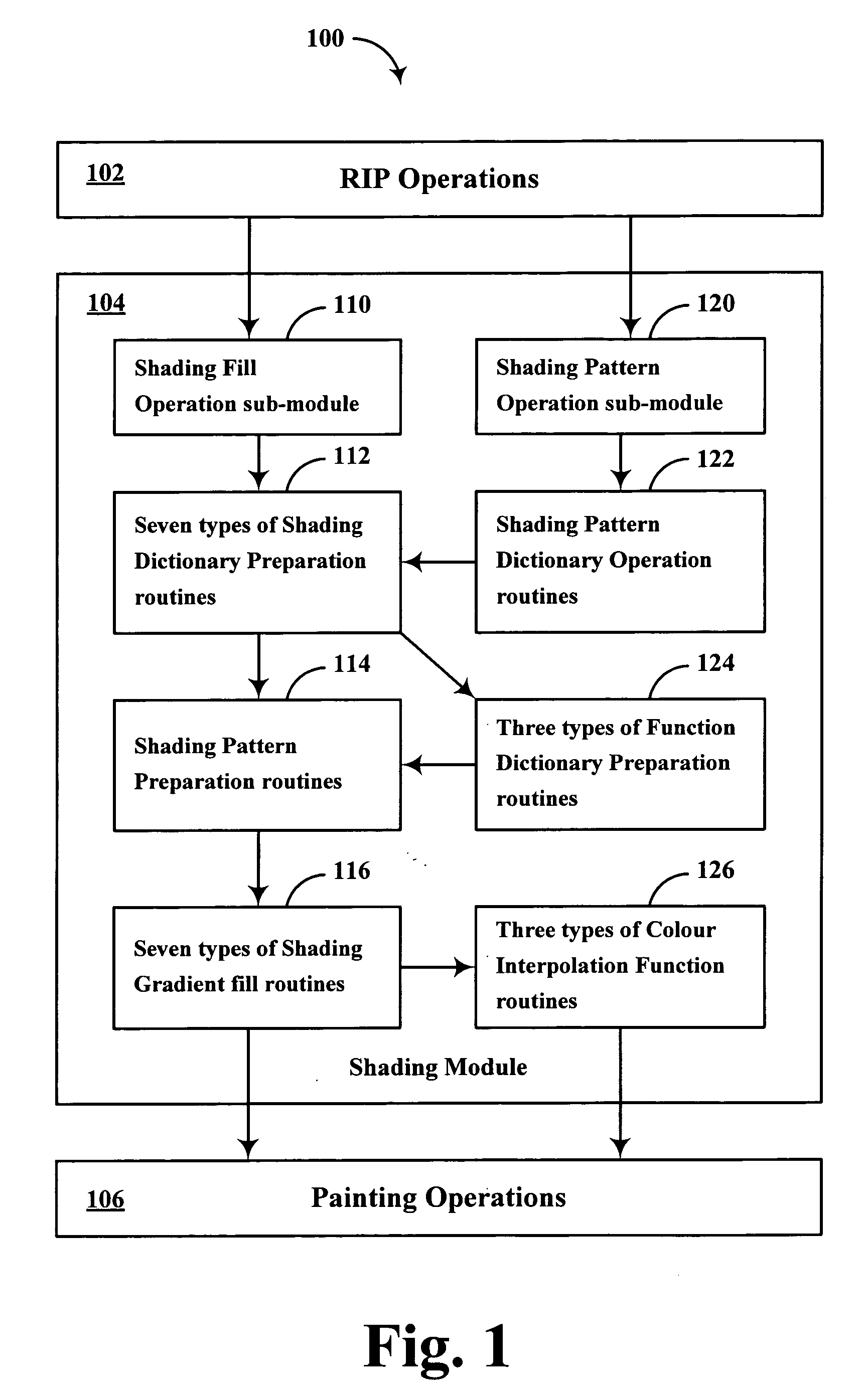
[0032] Referring to FIG. 1, in a raster graphics output device such as a printer or a display, the rasterisation of input visual information is performed via a raster image processor 102 contained within a control unit 100 of the device. Shading operations required for rasterisation of input data is usually performed within a shading module 104. Such a module contains predominantly two sub-modules, one for performing shading operation on areas bounded by simple geometric shapes and another for accomplishing shading pattern rendering operations on coverage areas with complicated geometrical boundaries. When painting a defined area with a shading pattern, a pattern dictionary is normally used, that describes the pattern type, unique identification number for identifying the particular pattern, Implementation key for specifying any implementation-dependent entries that are associated with the pattern and a shading definition, i.e., a shading dictionary. There are seven types of shading...


PUM


Abstract

Methods of mapping the shading dictionary parameters provided by a postscript language interpreter into device space coordinates and performing shading in the device space is disclosed. For radial shading, the shading transformation matrix representing the coordinate conversion from the shading space to device space is embedded within the shading mechanism parameters to directly compute the shading colour for a particular device space pixel, avoiding device coordinate transformations to the shading space. For triangle meshes based shading, the vertexes of the defined triangles are converted to device domain prior to performing interpolation for determining device pixel shading colour. For patch based shading, comprising of patches bounded by four Bezier curves, the Bezier curves are converted to the device domain to directly compute the corresponding shading parameter variables for a particular device pixel.

Description

BACKGROUND OF THE INVENTION [0001] This invention relates generally to raster graphics systems and more specifically to shading operations. [0002] In a raster graphics system, smooth shading in colour is used for two main operations. The first is to fill directly in a geometrically defined area, and the second is to produce shading patterns and then paint a defined area with the smooth colour transition. There is a plurality of methods to define such shading mechanisms. In a raster image processor related to a printer, the Postscript Language Reference Manual defines seven types of shading and parameters via shading dictionaries. The Postscript Language Reference, Third Edition, Adobe Systems, Inc., published by Addison Wesley Publishing, is hereby incorporated by reference. [0003] Shading provides a smooth transition between colours across an area to be painted, independent of the resolution of any particular output device and without specifying the number of steps in the colour tr...

Claims


Application Information

Patent Timeline
Patent Type & Authority Applications(United States)
IPC IPC(8): G06T15/50
CPCG06T15/87
Inventor JI, LILIAN
Owner KK TOSHIBA
Why Eureka
Try Eureka