
Method and apparatus for adjusting performance of logical volume copy destination

a technology of logical volume and performance adjustment, applied in the direction of redundant data error correction, input/output to record carriers, instruments, etc., can solve the problems of excessive consumption of memory for temporarily saving data and the need for extra standby tim

Inactive Publication Date: 2006-08-10
HITACHI LTD
View PDF16 Cites 21 Cited by
  • Summary
  • Abstract
  • Description
  • Claims
  • Application Information

AI Technical Summary

Benefits of technology

The present invention provides a failover type cluster system that maintains the performance of the overall system after a failover. It also allows for smooth and efficient copying of data between volumes. The system determines whether the destination volume after a failover is equal to or higher than the source volume before the failover and the destination volume is equal to or higher than the source volume during the copy. The system modifies the configuration of the destination volume if the condition(s) is not satisfied. The system also determines whether the source volume and destination volume satisfy the condition(s) and initiates the copy if they do. The invention helps to ensure the performance of the overall system is not compromised after a failover.

Problems solved by technology

If the performance of a destination volume is lower than the performance of a source volume during a snapshot or an inter-volume copy using a remote copy function, a memory for temporarily saving data can be excessively consumed by data which is transferred from the source volume to the destination volume, and an extra standby time is required until the data has been completely written into both volumes.

Method used


Image

  • Method and apparatus for adjusting performance of logical volume copy destination
  • Method and apparatus for adjusting performance of logical volume copy destination
  • Method and apparatus for adjusting performance of logical volume copy destination

Examples


first embodiment

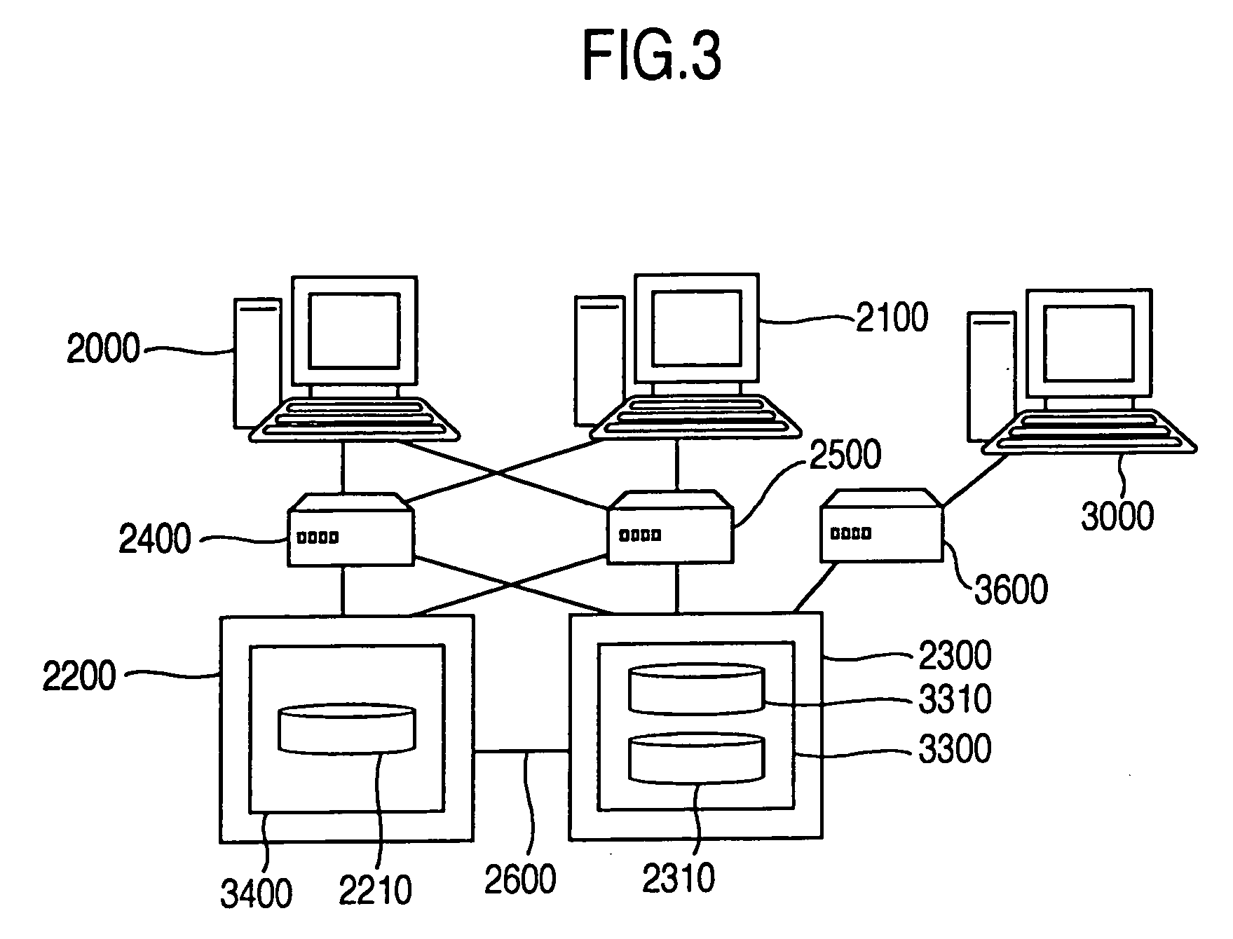
[0070]FIG. 3 shows a first embodiment in which the present invention is embodied in a storage apparatus 2200 and a storage apparatus 2300.

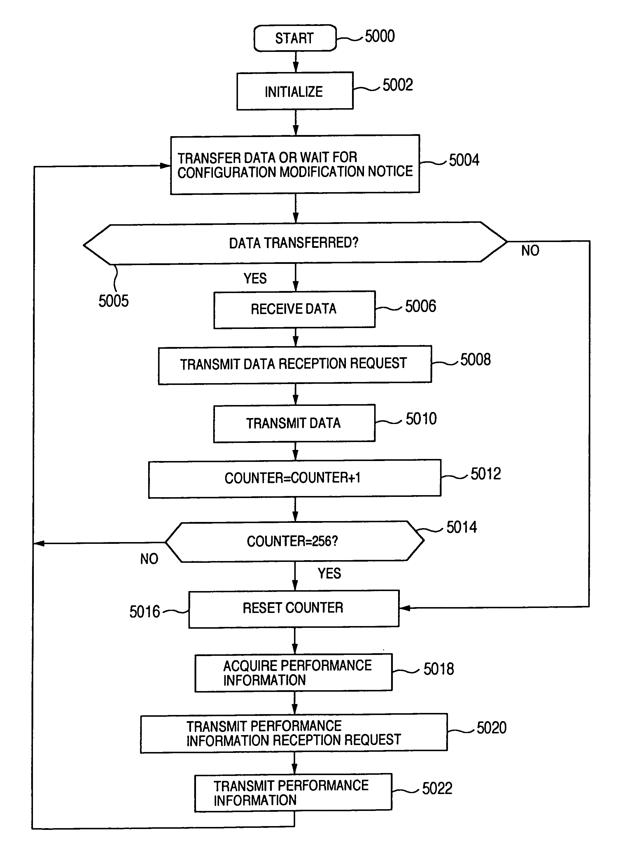
[0071] In the first embodiment, performance information within the storage apparatus 2200 in which a source volume 2210 is defined is transferred to the storage apparatus 2300 through a data communication path 2600 which is provided between the storage apparatus 2200 and storage apparatus 2300 in order to adjust the performance of a destination volume 2310 by moving as required a volume 3310 on the same parity group as the destination volume 2310 to another parity group. The performance adjustment may be triggered when the storage apparatus 2200 is modified in configuration, or may be made at least once every 256 data transfers from the source volume 3310 to the destination volume 2310.

[0072]FIG. 4 illustrates in a block diagram form the configuration in the storage apparatus 2200 and storage apparatus 2300 in the first embodiment. A parity group...

second embodiment

[0115] Next, in the present invention described below, an inter-volume copy is performed between volumes defined in the same storage apparatus using a snapshot function in a computer system, wherein a check is made every hour as to whether the performance of a destination volume after a failover can be degraded below the performance of a source volume before the failover, and volumes defined on the same parity group as the destination volume are moved to another parity group if such degradation is probably.

[0116]FIG. 12 illustrates the configuration of a system in the second embodiment.

[0117] A computer 12000 and a computer 12100 are connected to a communication device 12200 and a communication device 12300, respectively, and the communication device 12200 and communication device 12300 are connected to a communication unit 12440 and a communication unit 12450 in a storage apparatus 12400, respectively. A parity group 12410, a parity group 12420, and a parity group 12430 are define...

third embodiment

[0132] The system configuration in the third embodiment is similar to that illustrated in FIG. 3.

[0133]FIG. 15 illustrates in a block diagram form the configuration in the storage apparatus in the third embodiment. A parity group 15600, a parity group 15700, and a parity group 15800 are defined in the storage apparatus 15000, and a volume 15650 is defined in the parity group 15600, while a volume 15750 is defined in the parity group 15700.

[0134] A memory 15020 in the storage apparatus 15000 stores configuration information 15310 related to the volumes and parity groups in the storage apparatus 15000, performance information 15500 associated with the performance information on the volumes and parity groups in the storage apparatus 15000, and a performance prediction table 15550 for predicting the performance based on the performance information 15500. The memory 15020 further comprises configuration information management unit 15300 for managing the configuration information 15310, ...


PUM


Abstract

When data written into a volume (source volume) in a parity group in a storage apparatus is written into a volume (destination volume) in a parity group in a storage apparatus using a remote copy function, it is determined during the copy whether or not one or both of the following two specified conditions are satisfied for this set of volumes: (1) the performance of the destination volume after a failover is equal to or higher than the performance of the source volume before the failover; and (2) the performance of the destination volume is equal to or higher than the performance of the source volume during the copy. If the condition(s) is not satisfied, the storage apparatus in which the destination volume is defined is changed in configuration to satisfy the condition.

Description

BACKGROUND OF THE INVENTION [0001] The present invention relates to an adjustment for the performance of a logical volume within a storage apparatus, and more particularly to techniques for use with an inter-logical volume copy function for adjusting the performance of a destination logical volume in accordance with the performance of a source logical volume. [0002] It should be first noted that the “adjustment for the performance of a volume” used herein refers to a modification to the configuration in a storage apparatus in which the volume is defined such that the volume is provided with the performance higher than required performance. [0003] A technique called “RAID” (Redundant Array of Inexpensive Disks) is known for organizing two or more physical disks into a group to provide redundancy and improve the performance and reliability (see, for example, Jon William Toigo, “The Holy Grail of Data Storage Management,” Prentice Hall, 2000). [0004] For using a storage apparatus which...

Claims


Application Information

Patent Timeline
Patent Type & Authority Applications(United States)
IPC IPC(8): G06F12/16G06F3/06G06F11/10G06F12/00
CPCG06F11/1084G06F11/1096
Inventor SOEJIMA, KENICHIMIYAZAKI, SATOSHI
Owner HITACHI LTD
Learn More