Sling shot blow gun combination device

a combination device and sling shot technology, applied in the field of manual operation of weapons, can solve the problems of sight and collapsibility that have never been provided until now

Inactive Publication Date: 2006-08-17
MITCHELL EDWARD
View PDF9 Cites 9 Cited by
  • Summary
  • Abstract
  • Description
  • Claims
  • Application Information

AI Technical Summary

Problems solved by technology

Modern materials have been used for the basic tube approach; however, sights and collapsability have never been provided until now.

Method used


Image

  • Sling shot blow gun combination device
  • Sling shot blow gun combination device
  • Sling shot blow gun combination device

Examples


Embodiment Construction

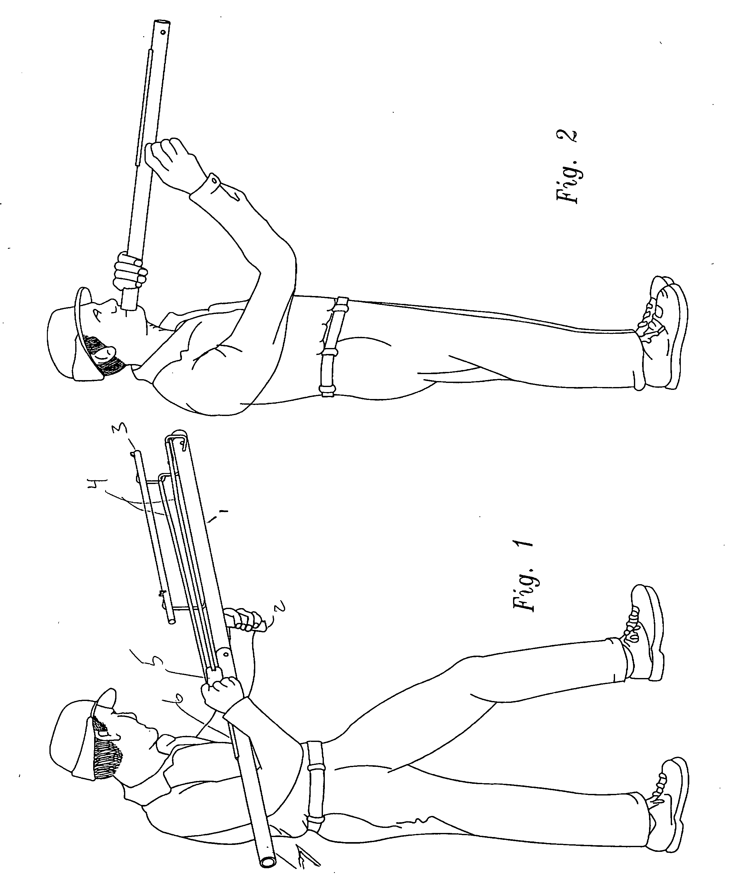
[0014]FIG. 1 shows the sling shot having a structural member 1 with a handle 2. The device has a sight bar 3 and elastic members 4 attached together at a pouch 5. The pouch with a projectile is drawn along a rail 6 to extend the elastic members 4 which stored energy will launch the projectile when released. The invention also has an extension 7 which permits a solid hold of the weapon. Note that the sight rod 3 is offset to clear the elastic members 4 but align with their point of aim.

[0015]FIG. 2 shows the extension 7 can be operated as blow gun. The rail 6 can be used as a sight in this configuration.

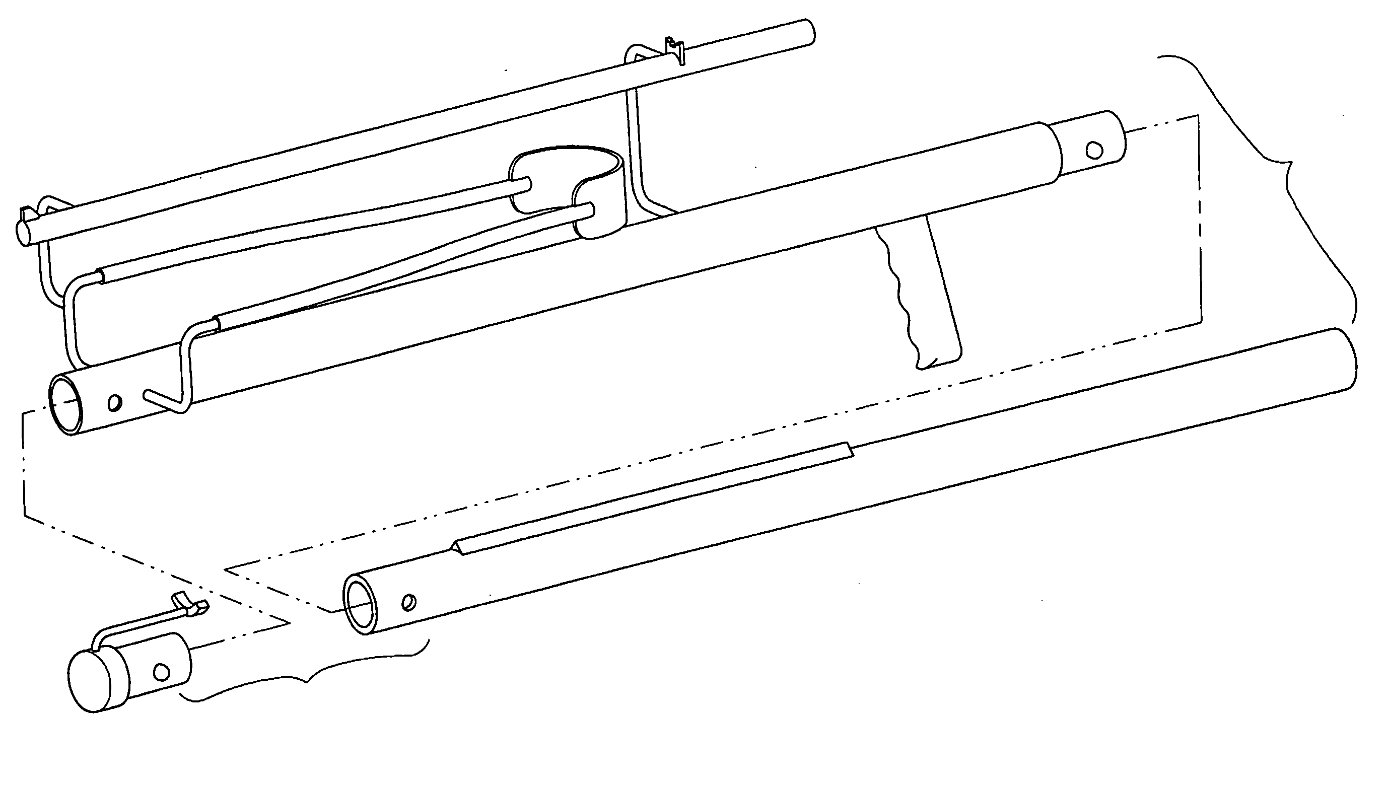
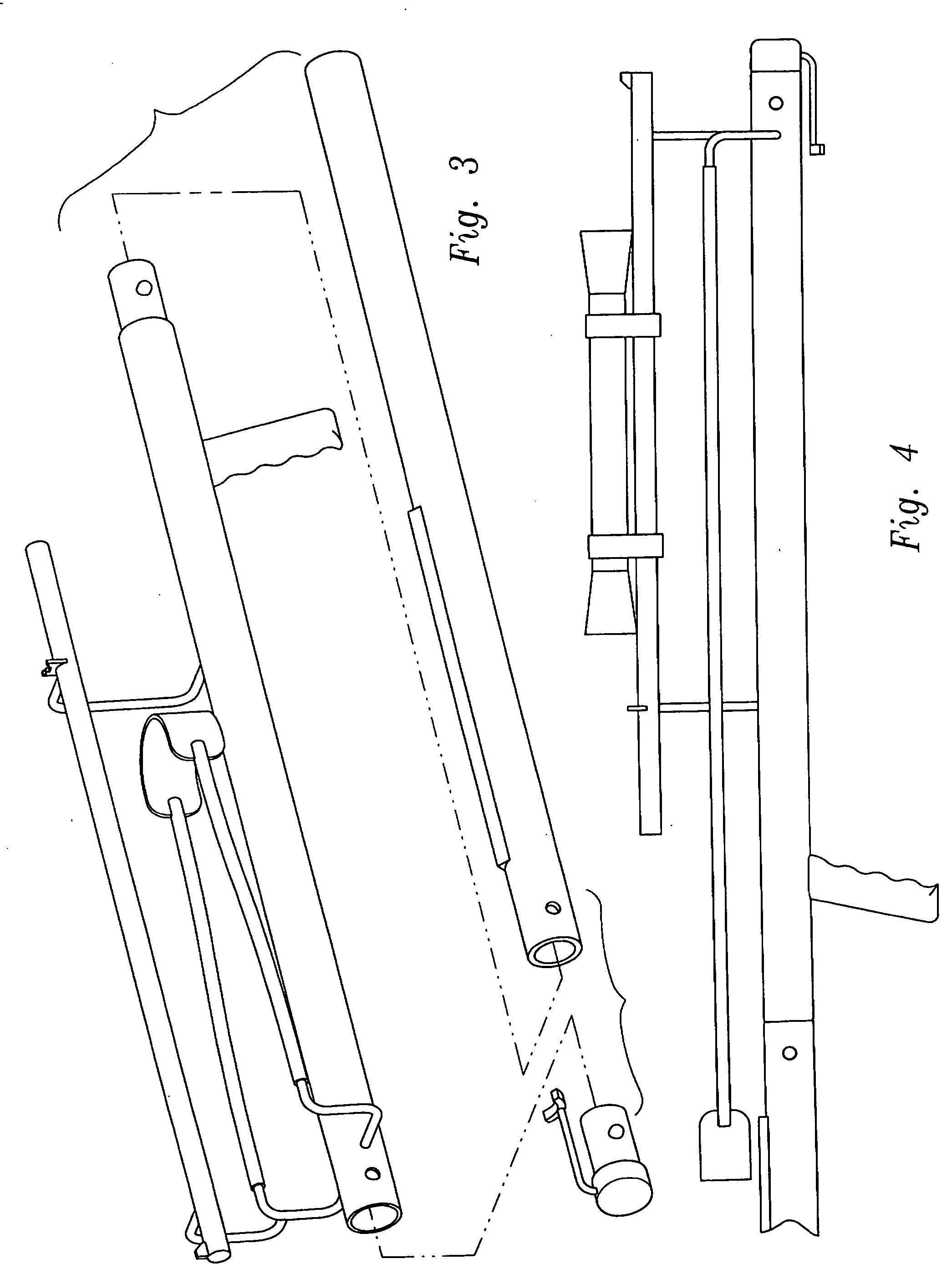
[0016]FIG. 3 shows an exploded view of the device. It further shows, along with FIG. 7, the button snap fitting mechanism for releasable attachment of members 1 and 7. FIG. 3 also shows an arrow support 8 which can be fitted into the end of member 1 and has a place to support an arrow shaft, the tail of which can be held in the pouch 5 and the sling becomes a compact arrow launcher....


PUM


Abstract

A unique human powered weapon for hunting or target shooting combining a sling shot, an arrow shooting device and a blow gun with sights and collapsability.

Description

BACKGROUND [0001] 1. Field of Invention [0002] This invention relates generally to the field of manually operated weapons. [0003] 2. Description of the Prior Art [0004] The prior art includes blow guns dating back hundreds of years. Modern materials have been used for the basic tube approach; however, sights and collapsability have never been provided until now. [0005] Further, the Applicant's invention is the first to provide a combination with sling shot. Applicant's sling shot provides a sight and a long sight radius for high accuracy. Applicant's invention further provides means to rest the weapon on a shoulder for a more accurate hold.BRIEF DESCRIPTION OF DRAWINGS [0006]FIG. 1 Perspective view of blow gun in situ. [0007]FIG. 2 Perspective view of sling shot orientation. [0008]FIG. 3 Exploded view of device. [0009]FIG. 4 Side view of device. [0010]FIG. 5 Top view of device. [0011]FIG. 6 Opposite side view of device. [0012]FIG. 7 Sectional view of attachment. [0013]FIG. 8 Front v...

Claims


Application Information

Patent Timeline
Patent Type & Authority Applications(United States)
IPC IPC(8): F41B3/02F41B1/00
CPCF41B1/00F41B3/02F41C23/00
Inventor MITCHELL, EDWARD
Owner MITCHELL EDWARD
Why Eureka
Try Eureka