Portable light device

Inactive Publication Date: 2006-08-24
CYBERLUX CORP
View PDF15 Cites 20 Cited by
  • Summary
  • Abstract
  • Description
  • Claims
  • Application Information

AI Technical Summary

Benefits of technology

[0007] In one embodiment, the lighting element assembly of the light device may include an array of light emitting diodes (“LEDs”) comprising a first LED disposed in reflective proximity to a narrowing lens or reflector that is adapted to provide a spot-light mode of illumination and a second LED that is adapted for a flood-light mode of illumination, wherein the first and second LEDs are disposed in electrical communication with a battery for supplying electrical energy to the array of LEDs, a control circuit, and a user interface system. In such embodiments, the control circuit may be configured to allow a user to engage the array of LEDs to illuminate in the spot-light mode of illumination, the flood-light mode of illumination, or a combination thereof, based upon input signals provided by the user interface system. In other embodiments, more or fewer first and second LEDs may be used.
[0008] In another embodiment, the light device may be comprised of an array of LEDs, a pivot member adapted to support the array of LEDs, and a positionable arm having an electro-mechanical hinge that is adapted to allow the pivot member to pivot a pivot range of at least 360 degrees relative to the positionable arm. The light device may also include a housing structured to at least partially enclose an electrical power system for providing electrical power to the array of LEDs, wherein the positionable arm is coupled to the housing and the electro-mechanical hinge is structured to provide uninterrupted electrical power from the power source to the array of LEDs while also allowing the pivot member to pivot over its full pivot range. In one embodiment, the electrical power system may include a battery. In another embodiment, the electrical power system may include one or

Problems solved by technology

Frequently, homes, offices and industrial plant facilities experience many types of emergency situations involving power failures where an interior or exterior area is rendered without light.
Such power failures may result from electrical short circuits, brownouts, f

Method used


Image

  • Portable light device
  • Portable light device
  • Portable light device

Examples


Embodiment Construction

[0031] The present invention now will be described more fully hereinafter with reference to the accompanying drawings, in which preferred embodiments of the invention are shown. This invention may, however, be embodied in many different forms and should not be construed as limited to the embodiments set forth herein; rather, these embodiments are provided so that this disclosure will be thorough and complete and will fully convey the scope of the invention to those skilled in the art. Like numbers refer to like elements throughout.

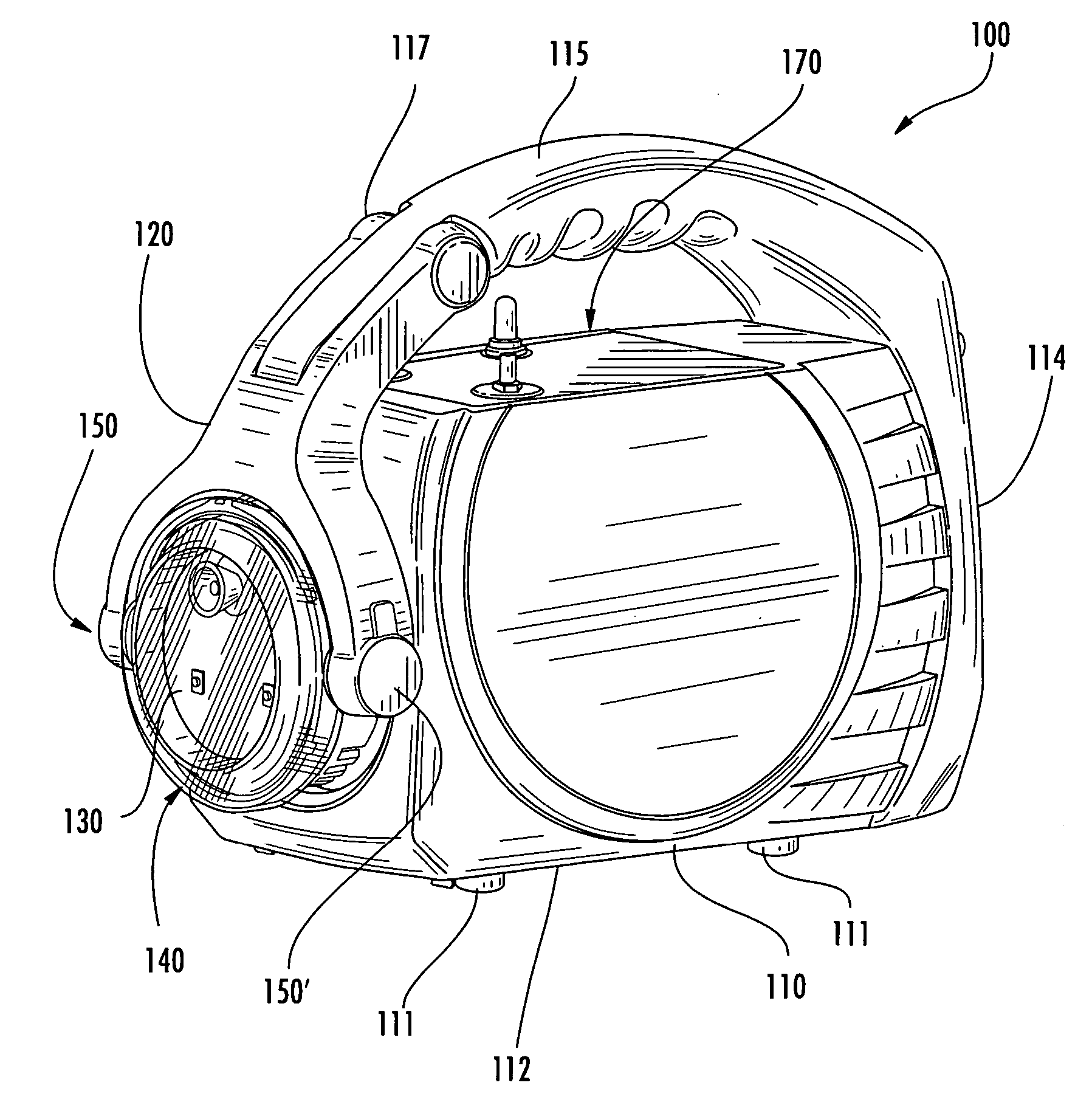
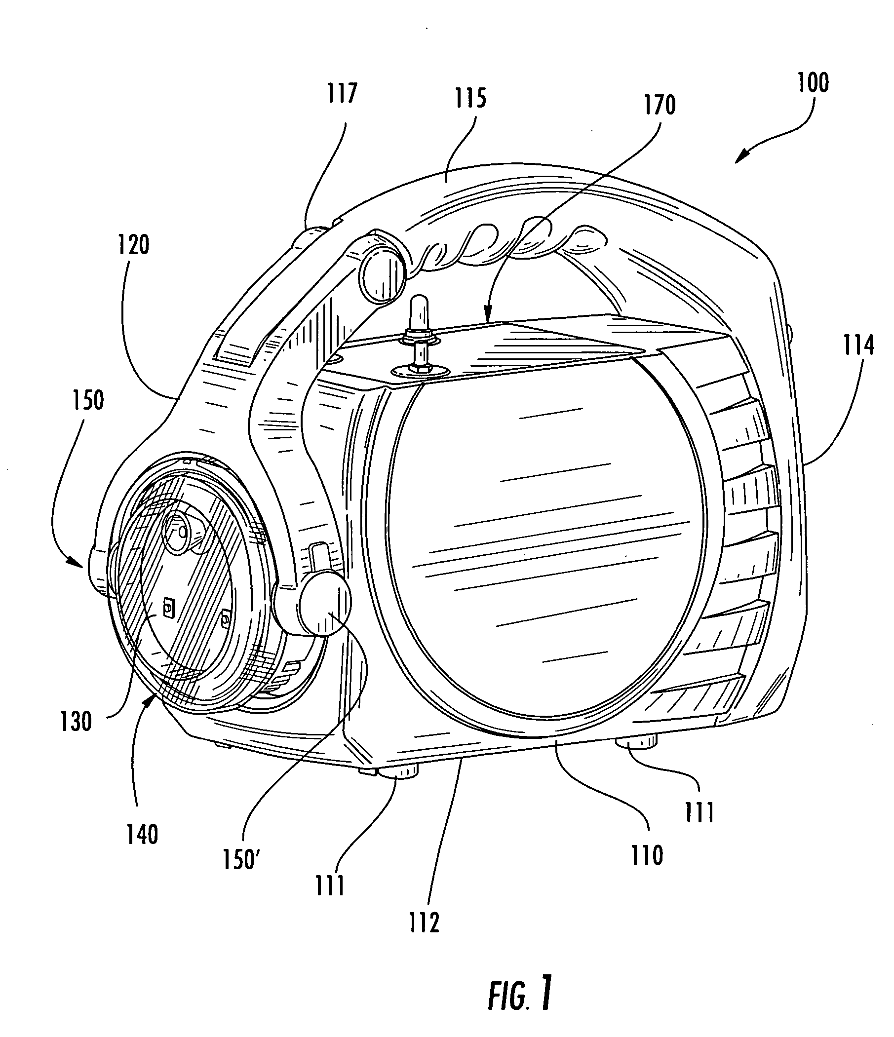
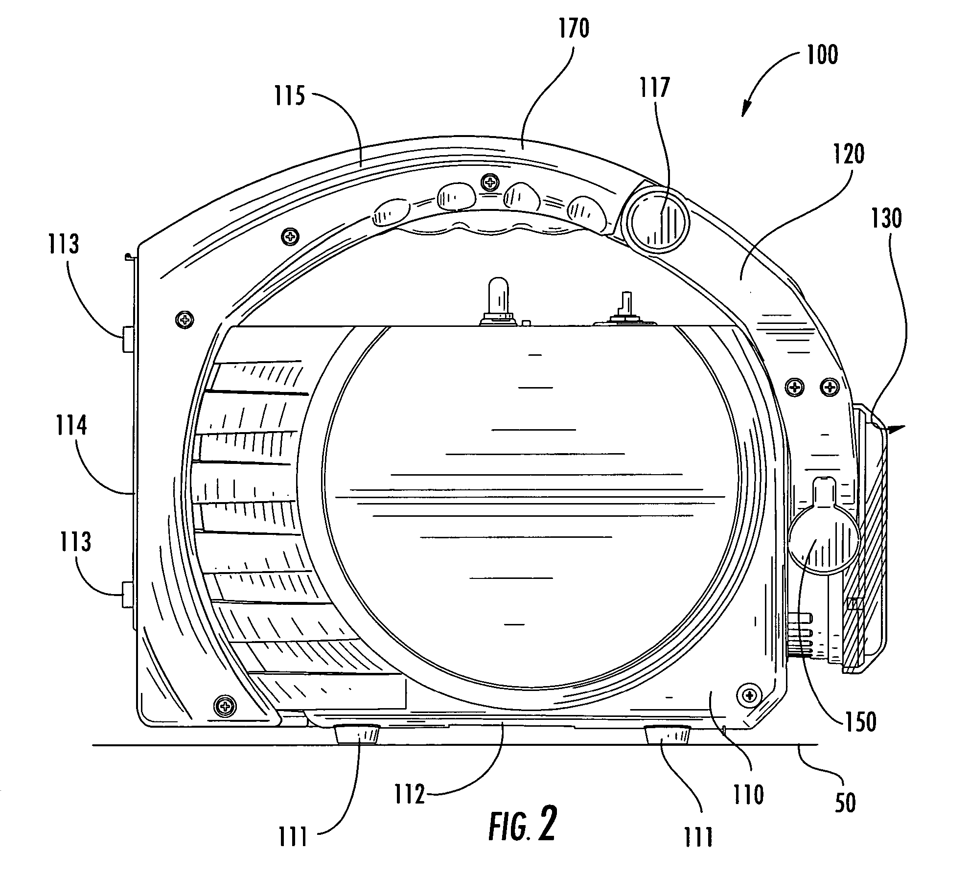
[0032] Referring to FIGS. 1 though 8 collectively, there is illustrated a light device 100 structured in accordance with various embodiments of the invention. In one embodiment, the light device 100 is comprised of a body 110, a handle 115, a user interface 170, and a positionable arm 120 that is structured to support a lighting element assembly 130 as shown. In one embodiment, the light device is configured to be portable and carried or otherwise manipul...


PUM


Abstract

The present invention provides a light device comprised of a body, a handle, a user interface, and a positionable arm that is structured to pivotally support a lighting element assembly. The light device may be configured to be portable and carried or otherwise manipulated by a user grasping the handle. In one embodiment, the body of the light device defines first and second support surfaces that are structured to stably support the weight of the light device in first and second illumination positions, respectively.

Description

CROSS-REFERENCE TO RELATED APPLICATIONS [0001] The present application claims priority to U.S. Provisional Application. No. 60 / 645,788 filed Jan. 21, 2005; the contents of which are incorporated herein in their entirety.FIELD OF THE INVENTION [0002] The present invention relates generally to the field of illumination and, more particularly, the invention relates to a solid state lighting source such as a portable light-emitting diode (“LED”) device that provides for directed, multi-level, illumination that may be controlled by a user to manage battery life. BACKGROUND OF THE INVENTION [0003] Frequently, homes, offices and industrial plant facilities experience many types of emergency situations involving power failures where an interior or exterior area is rendered without light. Such power failures may result from electrical short circuits, brownouts, fire, accidents, natural disasters (e.g., floods, hurricanes, tornados, etc.) or a planned shutdown of electricity within a facility...

Claims


Application Information

Patent Timeline
IPC IPC(8): F21V33/00
CPCF21L4/027F21L4/04F21L14/02F21V29/677F21V29/20Y10S362/80F21Y2101/02F21Y2115/10F21V29/67F21V29/70
Inventor EVANS, DONALD F.SCHMIDT, MARK D.ISELY, LARSONHATLEY, JEFFREYROTH, MICHAEL
Owner CYBERLUX CORP
Why Eureka
Try Eureka