Latching mechanism for forceps

Inactive Publication Date: 2006-08-24
SHERWOOD SERVICES AG
View PDF99 Cites 371 Cited by
  • Summary
  • Abstract
  • Description
  • Claims
  • Application Information

AI Technical Summary

Benefits of technology

[0008] The present disclosure relates to a surgical instrument having a slidable shaft with a proximal and a distal end, a housing operatively connected to the shaft and an actuation assembly having a first lever and a second lever, each of the first and second levers being pivotably connected to the shaft. The instrument further includes an end effector assembly operatively connected to the distal end of the shaft, the end effector assembly having a pair of opposing jaw members. A drive rod is disposed within the shaft and is connected to a housing connection, the drive rod being operable by the actuation assembly to actuate the opposing jaw members between open and closed positions. The instrument also includes a latching mechanism operatively associated with the actuation assembly and drive rod for maintaining the jaw members in the closed position, the latching mechanism including a biasing member housed between a spring collar and a spring mandrel.

Problems solved by technology

Additionally, typical interlocking ratchets require an unlatching torque to open the device.

Method used


Image

  • Latching mechanism for forceps
  • Latching mechanism for forceps
  • Latching mechanism for forceps

Examples


Embodiment Construction

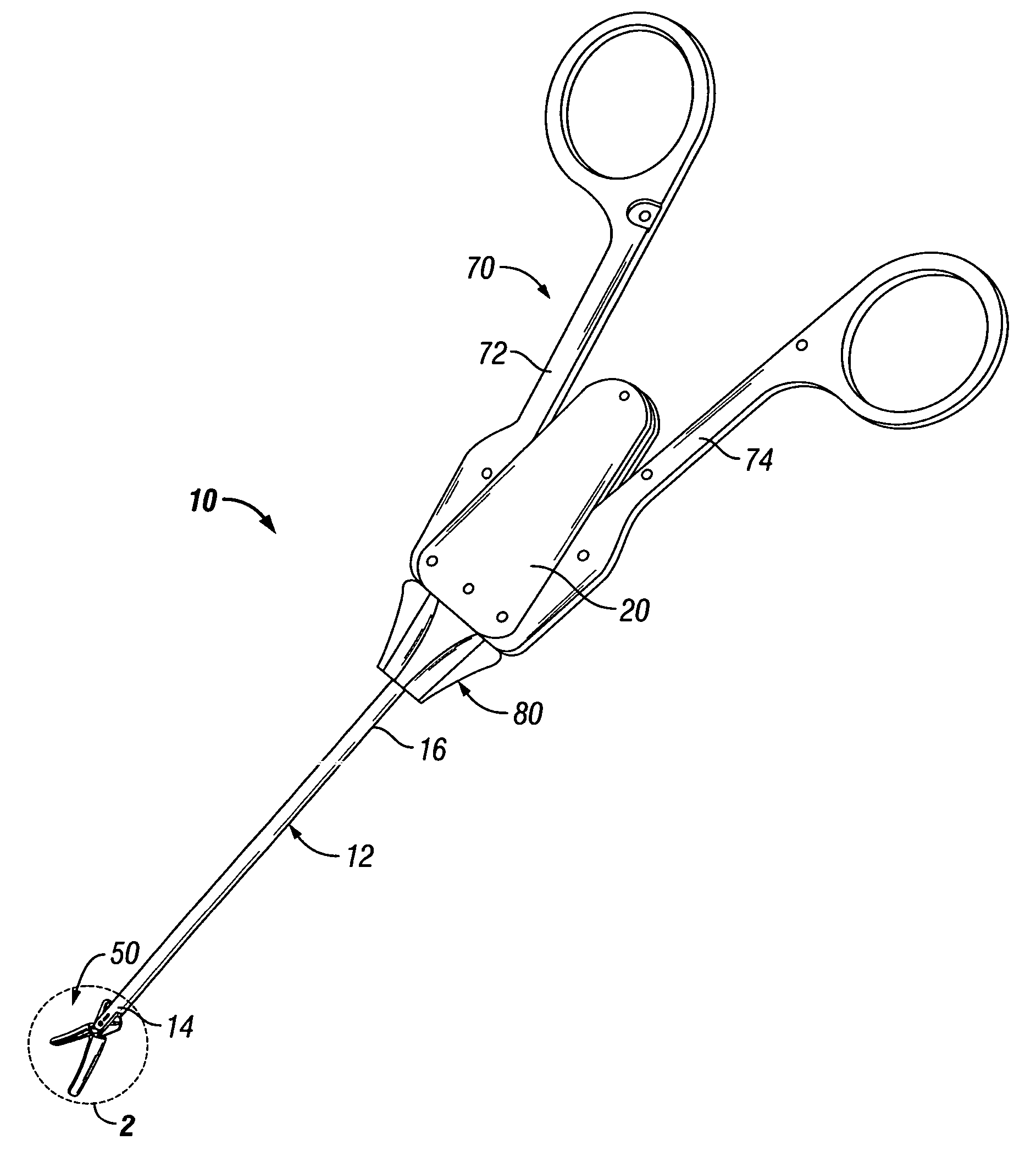
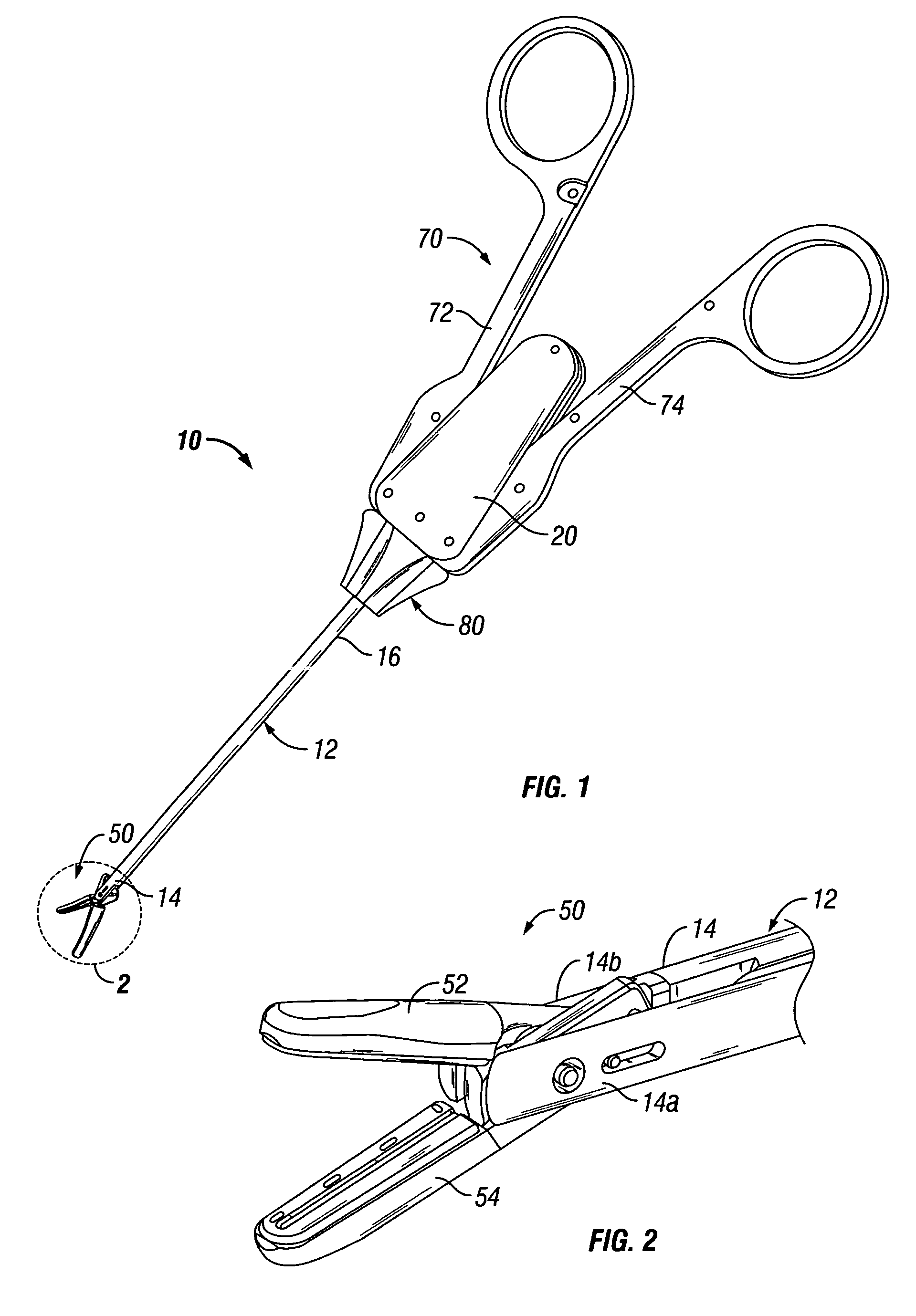
[0030] Referring now to FIGS. 1 and 2, one embodiment of a hemostat-type or forceps-type surgical instrument, in accordance with the present disclosure, is generally designated as 10. In the drawings and in the description that follows, the term “proximal”, as is traditional, will refer to the end of surgical instrument 10 that is closer to the user, while the term “distal” will refer to the end of surgical instrument 10 that is further from the user.

[0031] As seen in FIG. 1, surgical instrument 10 generally includes a housing 20, an actuating assembly 70 operatively associated with housing 20, and an end effector assembly 50 operatively associated with housing 20 and actuation assembly 70. End effector assembly 50 may function to grasp, seal and divide tubular vessels and vascular tissue. Although surgical instrument 10 is shown in FIGS. 1 and 2 as being configured for use in connection with endoscopic surgical procedures, an open-type surgical instrument (not shown) is also conte...


PUM


Abstract

The present disclosure relates to a surgical instrument that includes a slidable shaft having a proximal and a distal end and a housing coupled to the shaft. The instrument includes an actuation assembly having a first lever and a second lever, each of the first and second levers being pivotably connected to the shaft. The instrument further includes an end effector assembly coupled to the distal end of the shaft, the end effector assembly having a pair of opposing jaw members. The instrument may have a drive rod disposed within the shaft and connected to a housing connection, the drive rod being operable by the actuation assembly to actuate the opposing jaw members between open and closed positions. A latching mechanism is operatively associated with the actuation assembly and drive rod for maintaining the jaw members in the closed position, the latching mechanism including a biasing member housed between a spring collar and a spring mandrel.

Description

CROSS REFERENCE TO RELATED APPLICATIONS [0001] This application claims priority from U.S. Provisional Application Ser. No. 60 / 616, 973 filed on Oct. 8, 2004 and is a continuation-in-part of application Ser. No. 11 / 232,256, the contents of which are hereby incorporated by reference in their entirety.BACKGROUND [0002] 1. Technical Field [0003] The present disclosure relates to surgical instruments including hemostat-type and forceps-type surgical instruments for performing surgical functions and, more particularly, hemostat-type or forceps-type surgical instruments including improved latching mechanisms for opening and closing or otherwise operating an end effector of the surgical instrument. [0004] 2. Background of Related Art [0005] A hemostat or forceps is a simple plier-like tool which uses mechanical action between its jaws to constrict vessels and is commonly used in open surgical procedures to grasp, dissect and / or clamp tissue. Electrosurgical forceps utilize both mechanical c...

Claims


Application Information

Patent Timeline
Patent Type & Authority Applications(United States)
IPC IPC(8): A61B17/28
CPCA61B17/2909A61B2017/2922A61B2017/2946
Inventor HUSHKA, DYLANGARRISON, DAVID M.
Owner SHERWOOD SERVICES AG
Why Eureka
Try Eureka