Indurstrial robot controlling device

a robot control and industrial technology, applied in the direction of electric programme control, program control, dynamo-electric converter control, etc., can solve the problems of robots not being repaired/adjusted, motor cannot maintain the predetermined position, and other production facilities cannot opera

Inactive Publication Date: 2006-08-31
YASKAWA DENKI KK
View PDF4 Cites 26 Cited by
  • Summary
  • Abstract
  • Description
  • Claims
  • Application Information

AI Technical Summary

Benefits of technology

The patent describes a device that can select between signals from a control unit and a manual brake releasing input member to operate a relay. The device can also select between the control unit and the manual brake releasing input member depending on whether the motor is running or not. The manual brake releasing input member is on a handheld device and is used as an external signal. The technical effect of this invention is to provide a convenient and flexible way to control the brakes of a vehicle.

Problems solved by technology

The technical problem addressed in this patent is the inability of the motor in an articulated industrial-purpose robot to maintain a predetermined position when the driving power supply is cut off, and the need for an electromagnetic brake to prevent unintended movement. However, the existing brake circuit design using a single contact can lead to failure of the robot if the contact fuses, and the brake releasing-purpose power supply must be provided inside the robot control apparatus, making it difficult to make the apparatus compact and increasing manufacturing costs.

Method used


Image

  • Indurstrial robot controlling device
  • Indurstrial robot controlling device
  • Indurstrial robot controlling device

Examples


Embodiment Construction

[0018] Now, a description is made of a concrete embodiment of the present invention with reference to drawings.

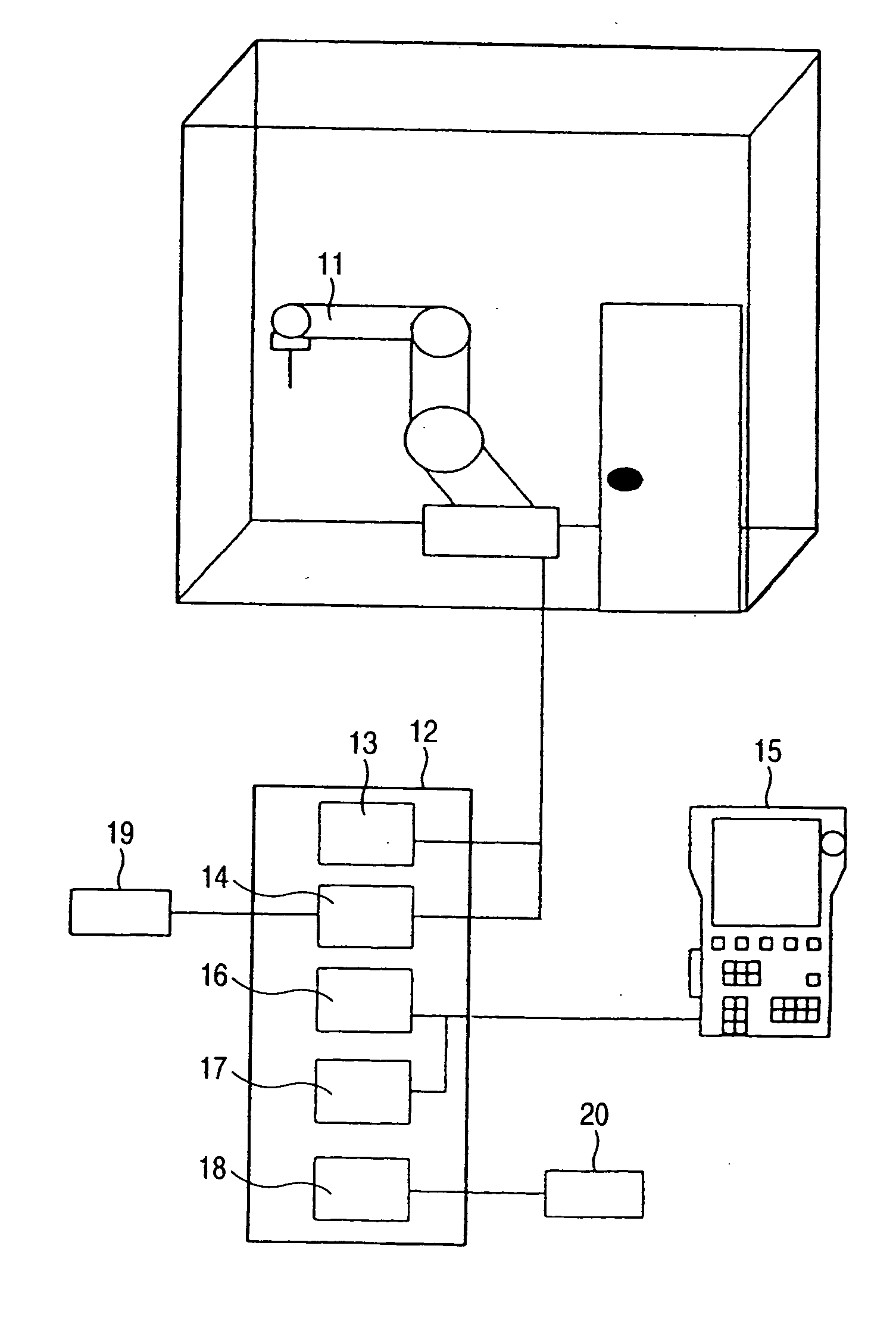
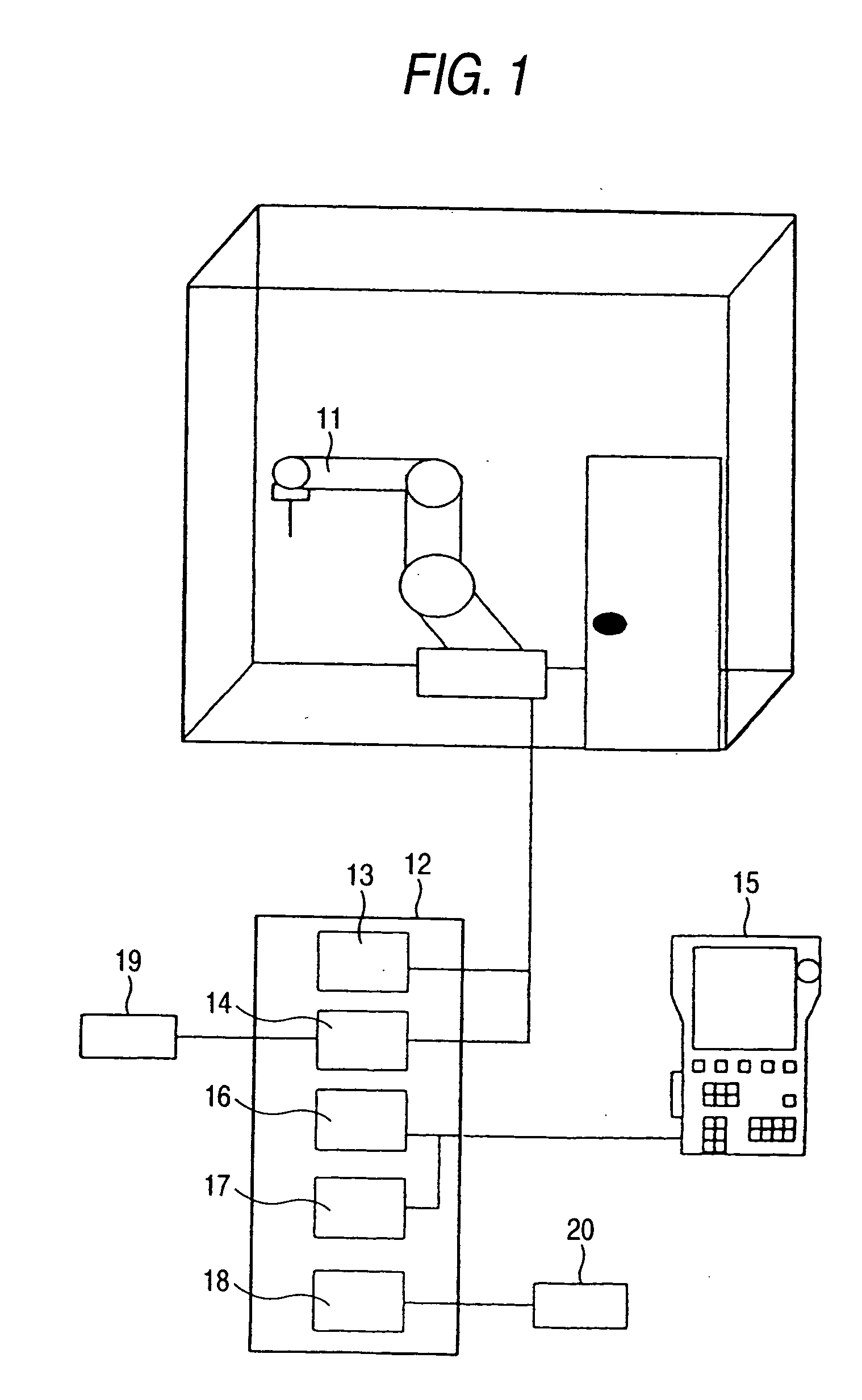
[0019]FIG. 1 is a structural diagram of a robot system which indicates an embodiment of the present invention. In this drawing, reference numeral 11 shows a robot which should be controlled, and reference numeral 12 indicates a robot control apparatus for controlling the robot 11. The robot control apparatus 12 is provided with a drive apparatus 13, a brake control unit 14, a driving power supply pre-stage control appliance 16, a control unit 14, and an input / output unit 18. The drive apparatus 13 drives a motor (not shown) of the robot 11. The brake control unit 14 controls a brake of the above-explained motor. The driving power supply pre-stage control appliance 16 judges a turn-ON condition of the driving power supply in response to an emergency stop signal entered from an external unit, or a control signal entered from a pendant 15. The input / output unit 18 inputs and ...


PUM


Abstract

Since a release voltage to a brake is applied by a plurality of series-connected contacts and at least one contact is a normally open contact of a relay for controlling a driving power supply of a motor, a control apparatus having a high safety characteristic for an industrial-purpose robot is provided, while even when fusion of a contact happens to occur, the control apparatus can firmly interrupt the application of the release voltage to the brake. Also, the control apparatus for the industrial-purpose robot is provided which need not be equipped with a power supply for releasing the brake by an operator in a manual manner.
To this end, in a control apparatus of an industrial-purpose robot (11) equipped with an electromagnetic type brake (23) which locks a shaft of a motor, the control apparatus is provided with a first relay contact (24) which is closed when the electromagnetic type brake (23) is released, and a second relay contact (22) which is closed when driving electric power is supplied to the motor; and the first relay contact (24), the second relay contact (22), and the electromagnetic type brake (23) are series-connected to a drive-purpose power supply (27) of the electromagnetic type brake (23).

Description


Claims


Application Information

Patent Timeline
Owner YASKAWA DENKI KK
Why Eureka
Try Eureka