Hand-carried weapon having a remote visual display

Inactive Publication Date: 2006-09-07
UNITED STATES OF AMERICA THE AS REPRESENTED BY THE SEC OF THE ARMY
View PDF12 Cites 20 Cited by
  • Summary
  • Abstract
  • Description
  • Claims
  • Application Information

AI Technical Summary

Benefits of technology

[0008] To sight the hand-carried weapon without having to look through the sight, the system of the present invention further includes a remote visual display. The remote visual display is preferably mounted to a helmet, which further frees the operator's hand for firing of the weapon. An interconnecting means such as a cable connects the remote visual display to the thermal sight. On one end of the

Problems solved by technology

However, the bulk of the thermal sight (Specifically, the height at which it sits above the weapon) makes it difficult for the user to look through the sight when firing the weapon.
When the user fires the weapon from the prone position, this condition worsens, and the user may actually have to expose oneself to hostile fire.
Otherwise, the recoil from the weapon causes the weapon to strike the user in the face with sufficient force to give the user a black eye.
Because of these constraints, it is very difficult to use thermal sights to aim hand-carried weapons, and thermal sights are generally used only for observation or when the hand-carried weapon is mounted in a static position.

Method used


Image

  • Hand-carried weapon having a remote visual display
  • Hand-carried weapon having a remote visual display
  • Hand-carried weapon having a remote visual display

Examples


Embodiment Construction

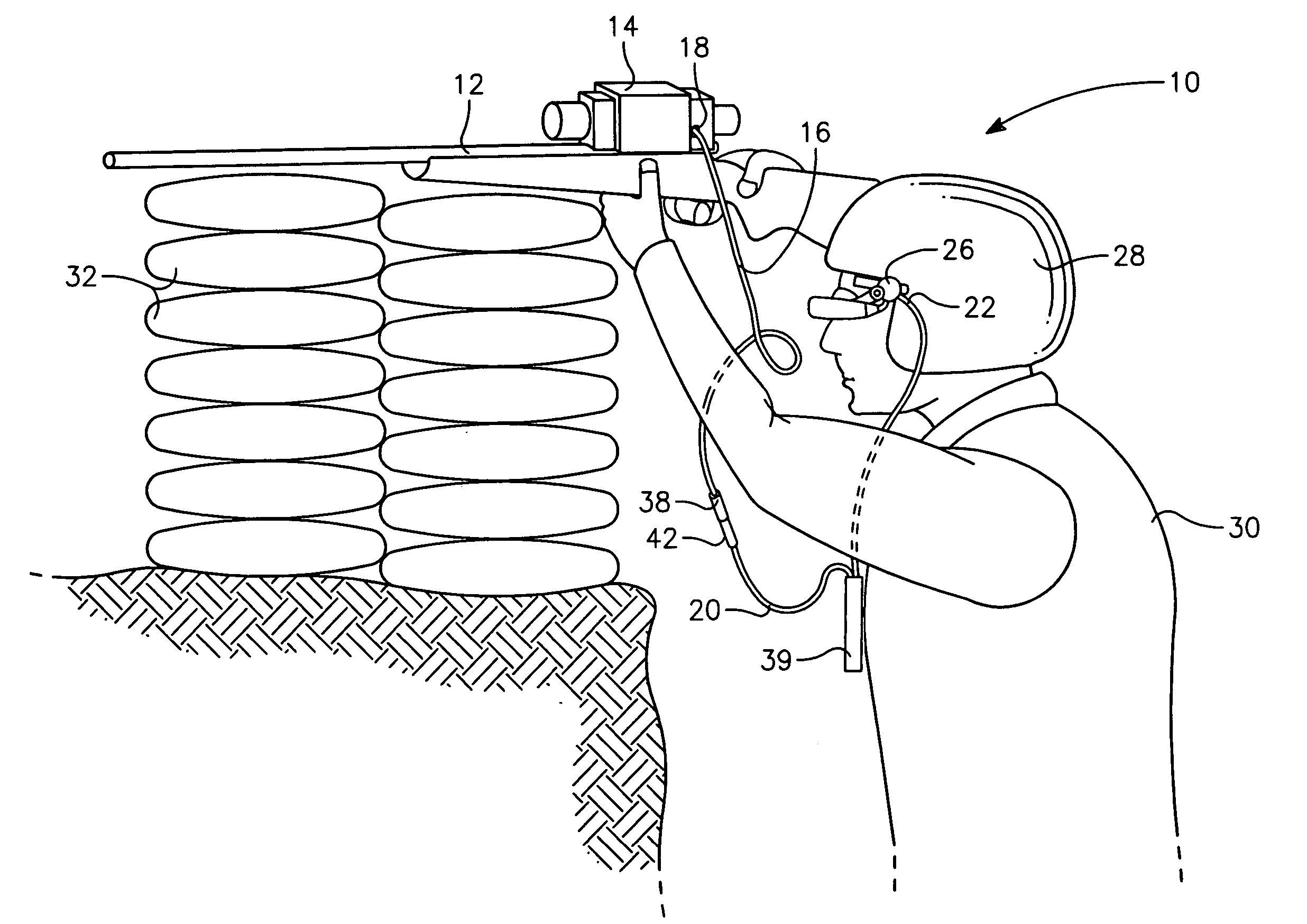
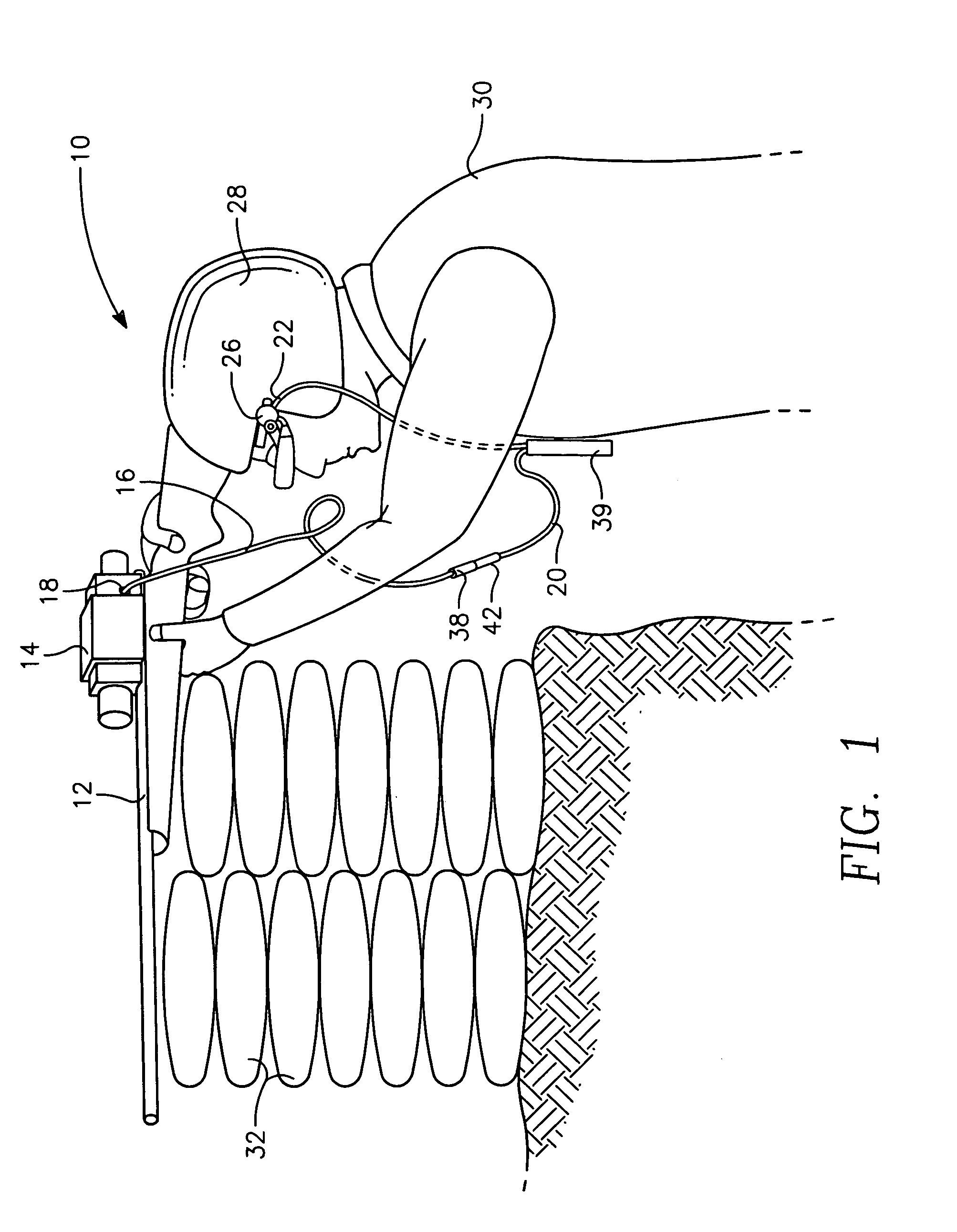
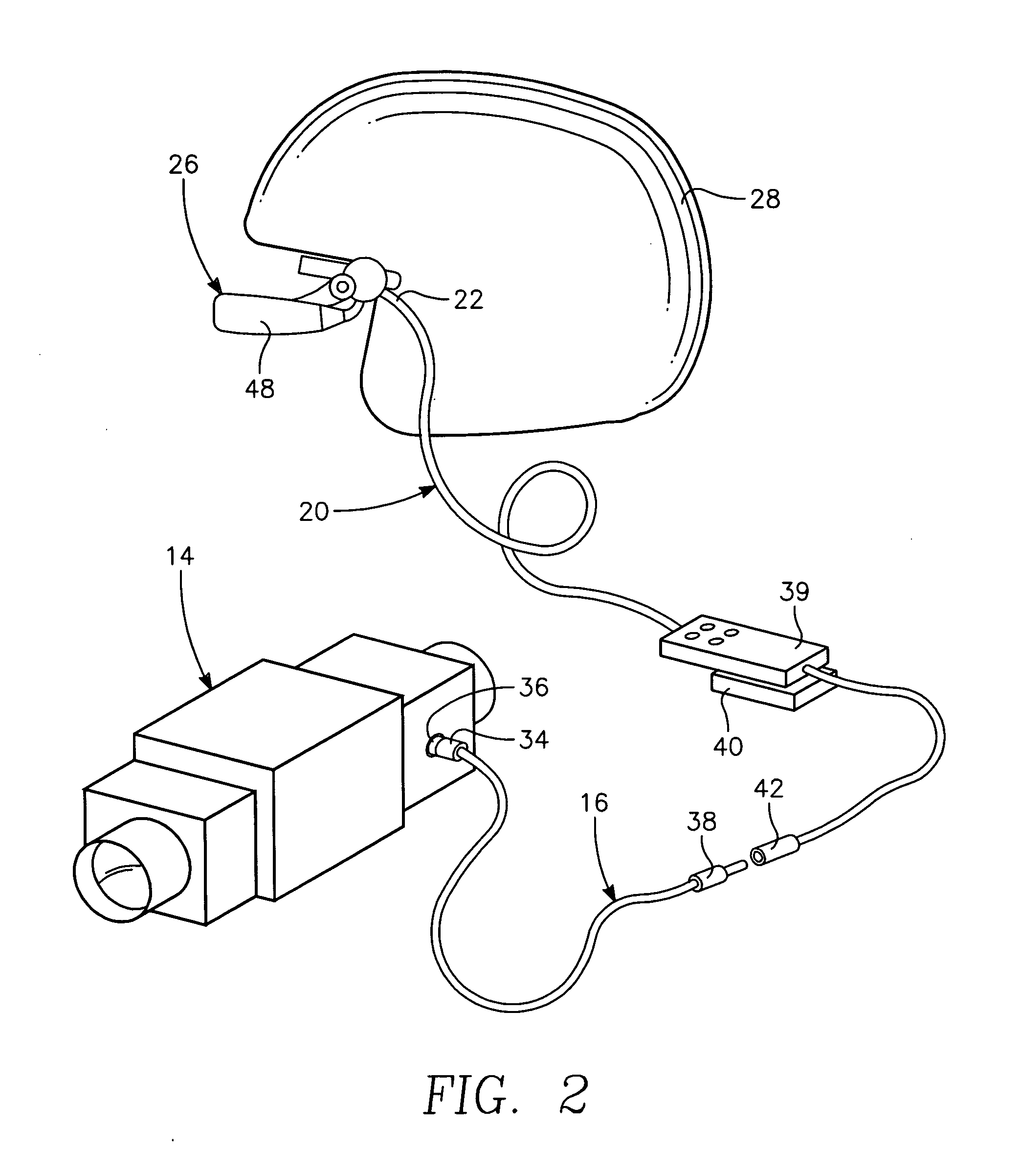
[0014] Referring now to the Figures, the weapon system of the present invention is shown and is generally depicted by reference character 10. In brief overview, and as shown primarily in FIGS. 1 and 2, the system includes a hand-carried weapon 12, and a sight 14 that is mounted to the weapon. A remote visual display 26 is connected to the sight via a first video cable 16 and a second video cable 20 in a manner more fully described hereinafter. The display 26 is also mounted on a helmet 28 which is worn by the user 30. With this configuration, the user can look through the remote visual display to sight the weapon from behind cover 32.

[0015] Preferably, the hand-carried weapons if a rifle, although hand-carried weapons such as pistols can be used to practice the invention. Most sights which can be mounted to a hand-carried weapon are suitable for use with the present invention, provided the sight has a video output port for connection to the display 26. Preferably, the Thermal Weapo...


PUM


Abstract

A weapon system in accordance with the present invention includes a rifle, a thermal sight that is mounted to the rifle, a helmet and a remote visual display that mounted to the helmet. The weapons system further includes an interconnecting means that connects the remote visual display to the thermal sight. The interconnecting means includes a first cable that is semi-permanently connected to a video port on the thermal sight and has a free end that terminates at a jack. A second video cable is permanently wired to the remote visual display and has a free end that terminates at a plug. To sight the hand-carried weapon without having to look through the sight, the jack is inserted into the plug, to thereby provide video from the sight to the remote visual display. The user fired the rifle from behind cover by viewing the sight reticles through the remote display.

Description

GOVERNMENT INTEREST [0001] The invention described herein may be manufactured, used, sold, imported, and / or licensed by or for the Government of the United States of America.FIELD OF THE INVENTION [0002] The present invention applies generally to weapon sights. More particularly, the present invention is useful as a thermal sight with a remote visual display that allows an operator to sight a hand-carried weapon without having to physically look through the sight. BACKGROUND OF THE INVENTION [0003] Thermal, or infrared (IR), sights that are adapted to be mounted on portable weapons systems are well known in the prior art. Thermal sights are useful for obtaining targeting data in the IR spectrum. In some cases, these sights are mounted to hand-carried weapons such as rifles. However, the bulk of the thermal sight (Specifically, the height at which it sits above the weapon) makes it difficult for the user to look through the sight when firing the weapon. When the user fires the weapon...

Claims


Application Information

Patent Timeline
IPC IPC(8): F41G1/38
CPCF41G1/38F41G3/165
Inventor LEE, YAU S.ROBERTS, MARK A.
Owner UNITED STATES OF AMERICA THE AS REPRESENTED BY THE SEC OF THE ARMY
Why Eureka
Try Eureka