
Casing packoff system

a packoff system and casing technology, applied in the direction of sealing/packing, fluid removal, borehole/well accessories, etc., can solve the problems of loss of desirable fluids, perforation of casings, and operator's very few options for remediating wells

Inactive Publication Date: 2006-09-07
DIRECTIONAL SYST
View PDF9 Cites 1 Cited by
  • Summary
  • Abstract
  • Description
  • Claims
  • Application Information

AI Technical Summary

Benefits of technology

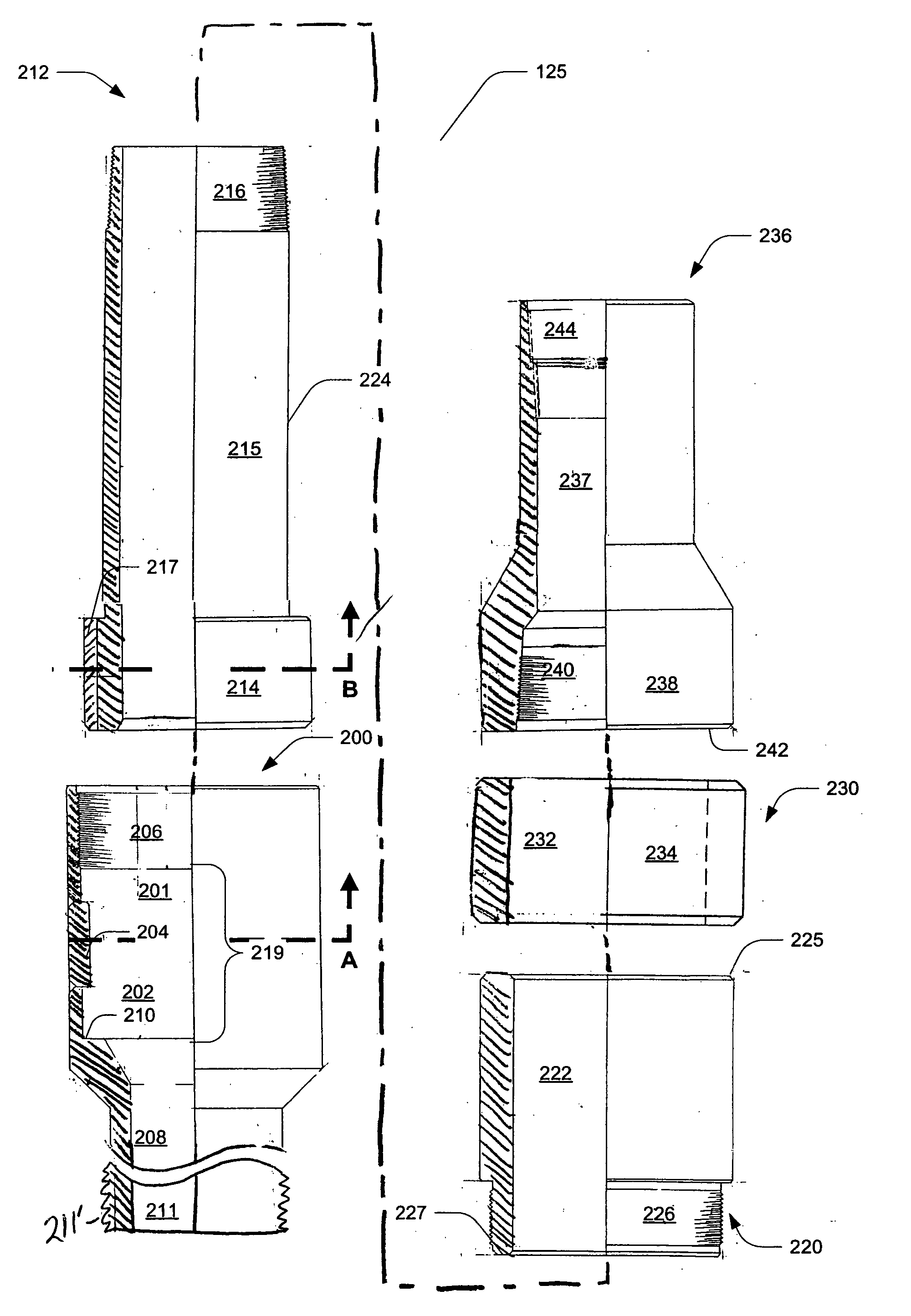
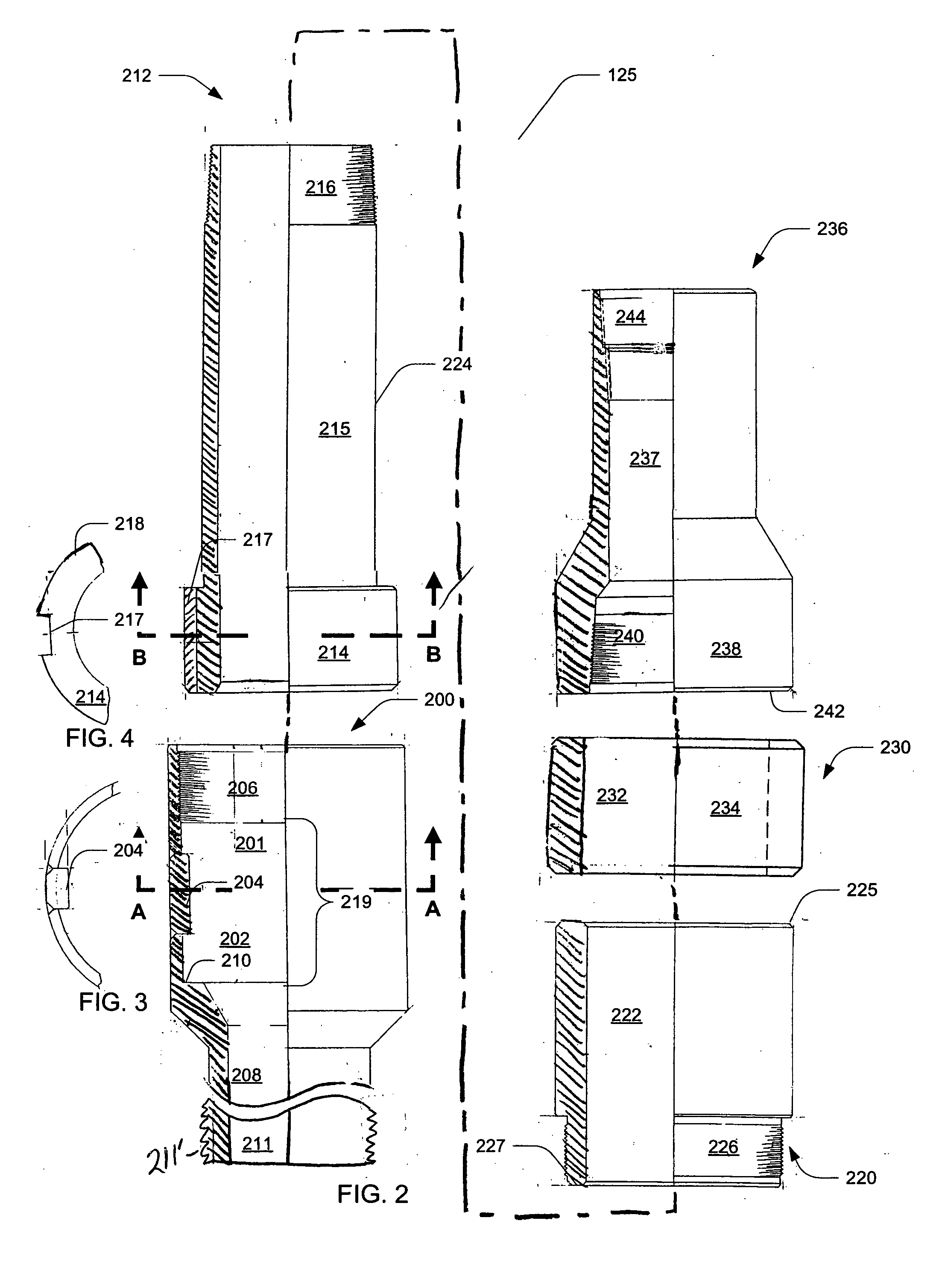
[0005] In one embodiment, the present invention is a well casing packer that includes a seal mandrel having a first coupler, a second coupler, and a neck extending between the first coupler and the second coupler. A first compression body is slidably coupled to the seal mandrel at the first coupler. A second compression body is connected to the seal mandrel, and a compression lock ring connected to the first compression body. A packer seal is disposed in surrounding relation to a portion of the neck of the seal mandrel and between the second compression body and the compression lock ring, such that a longitudinal movement of the seal mandrel with respect to the first compression body allows the second compression body and the compression lock ring to longitudinally compress and radially expand the packer seal.

Problems solved by technology

Over time, the casing may develop perforations because of the effects of corrosion or mechanical damage caused by tripping tubulars and downhole tools through the casing.
These openings may allow undesirable formation fluids to enter the well bore.
More importantly, these perforations may allow desirable fluids, such as production fluids from lower formations or drilling fluids, to leak from the casing into a formation, thus causing a loss of these desirable fluids.
Once a casing has developed such leaks, an operator has very few options to remediate the well.
As these options are expensive, the well may simply be abandoned if it is a marginal producer.
In this case, both squeeze jobs and re-casing of the producing zone are too permanent as these solutions will require additional reworking of the well in the currently producing zone to bring the well back into production.

Method used


Image

  • Casing packoff system
  • Casing packoff system
  • Casing packoff system

Examples


Embodiment Construction

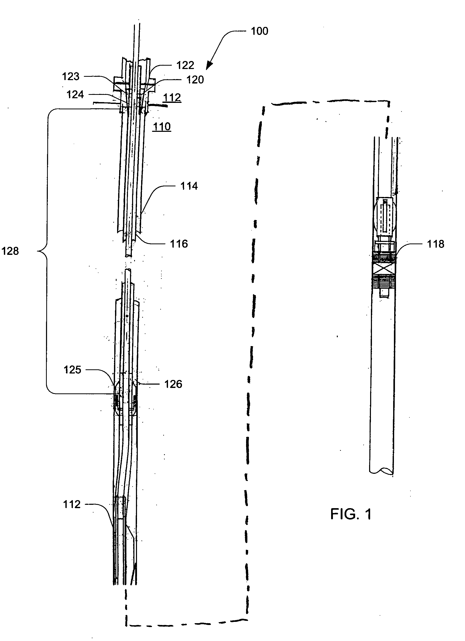
[0015]FIG. 1 is an exploded semi-diagrammatic view of a well, well casing, a casing packoff system, and a bottom anchor in accordance with an exemplary embodiment of the present invention. A well 110 extends downwardly from the surface of the earth 112 to a zone deep within the earth from which oil, gas or another fluid is to be produced. The well is lined along its vertical extent by a conventional well casing 114. The well may be one in which the well casing has deteriorated or one in which an operator wishes to enhance production by performing additional drilling operations as previously described.

[0016] The equipment utilized to rework the well includes an elongated vertical string of pipe or conductor 116 which has an external diameter less than the internal diameter of the casing of the well. The conductor is formed in a conventional manner of a series of pipe sections threadedly connected together, and is of a length to extend downwardly from the surface of the earth to the ...


PUM


Abstract

A well casing packer is provided that includes a seal mandrel having a first coupler, a second coupler, and a neck extending between the first coupler and the second coupler. A first compression body is slidably coupled to the seal mandrel at the first coupler. A second compression body is connected to the seal mandrel, and a compression lock ring connected to the first compression body. A packer seal is disposed in surrounding relation to a portion of the neck of the seal mandrel and between the second compression body and the compression lock ring, such that a longitudinal movement of the seal mandrel with respect to the first compression body allows the second compression body and the compression lock ring to longitudinally compress and radially expand the packer seal.

Description

BACKGROUND OF THE INVENTION [0001] This invention pertains generally to well workover systems and more specifically to casing packoff systems used during a well workover process. [0002] Most oil wells are constructed of an outer casing through which production tubulars are passed. The casing maintains the integrity of the well by preventing the formation material through which the well passes from entering the well bore of the well. Over time, the casing may develop perforations because of the effects of corrosion or mechanical damage caused by tripping tubulars and downhole tools through the casing. These openings may allow undesirable formation fluids to enter the well bore. More importantly, these perforations may allow desirable fluids, such as production fluids from lower formations or drilling fluids, to leak from the casing into a formation, thus causing a loss of these desirable fluids. [0003] Once a casing has developed such leaks, an operator has very few options to remedi...

Claims


Application Information

Patent Timeline
IPC IPC(8): E21B33/12
CPCE21B33/124E21B33/128
Inventor MURRAY, JAMES W.
Owner DIRECTIONAL SYST
Learn More