Planar light source and planar lighting apparatus

a light source and lighting technology, applied in lighting and heating apparatus, instruments, lenses, etc., can solve the problems of difficult to achieve the appropriate brightness, uniform light emission, and difficult to produce a large light diffuser, so as to prevent the occurrence of bright lines, suitable brightness, suitable uniform luminescence

Active Publication Date: 2006-09-07
NICHIA CORP
View PDF13 Cites 89 Cited by
  • Summary
  • Abstract
  • Description
  • Claims
  • Application Information

AI Technical Summary

Benefits of technology

[0013] According to the planar light source of the present invention, even if structure includes no light-guide plate is employed in a display device or the like, the action of guiding the light in planar fashion can be improved. In addition, it is realized to prevent the occurrence of bright lines and bright spots as well as color unevenness, and suitable brightness and suitable uniform luminescence can be realized. Moreover, the planar light source which has higher brightness, uniform luminescence, higher color mixing property with sufficient balance can be obtained. This allows the planar light source to be more lightweight, thinner and low power consumption.

Problems solved by technology

This is because it is difficult to produce a large light diffuser, and large display devices need to be made thinner and more lightweight.
Ironically, because of their poor temperature characteristics at low temperatures, fluorescent lamps have to be heated with a nearby heater despite the fact that they are used in a refrigerator.
However, when the core light source is a point light source, that is, zero-dimensional, the dimension has to be raised by two, so it is difficult to attain the appropriate brightness, uniform light emission, and so forth.
Specifically, when a light emitting diode constitutes a planar light source whose structure includes no light-guide plate, the portions located directly above the light emitting diode become bright spots, and it is difficult to make the light be emitted uniformly throughout the plane.
Also, when red, blue, and green light emitting diode chips are separately packaged and then combined to produce white light, color unevenness results.
Also, with a display refrigerator, the whole front is covered with glass, and a light source cannot be installed at this glass portion.
Therefore, due to structural limitations, this requires the use of a system in which light emitting diodes are installed vertically at the edges of sliding doors.
In this case, emitting the light over a wider range has been attempted by attaching a side emitter lens or a Lambertian lens to every light emitting diode, but it is difficult to prevent the occurrence of bright lines and bright spots due to the difference in optical paths attributable to the difference in the physical distances from the light emitting diode.

Method used


Image

  • Planar light source and planar lighting apparatus
  • Planar light source and planar lighting apparatus
  • Planar light source and planar lighting apparatus

Examples


working example 1

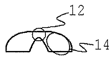
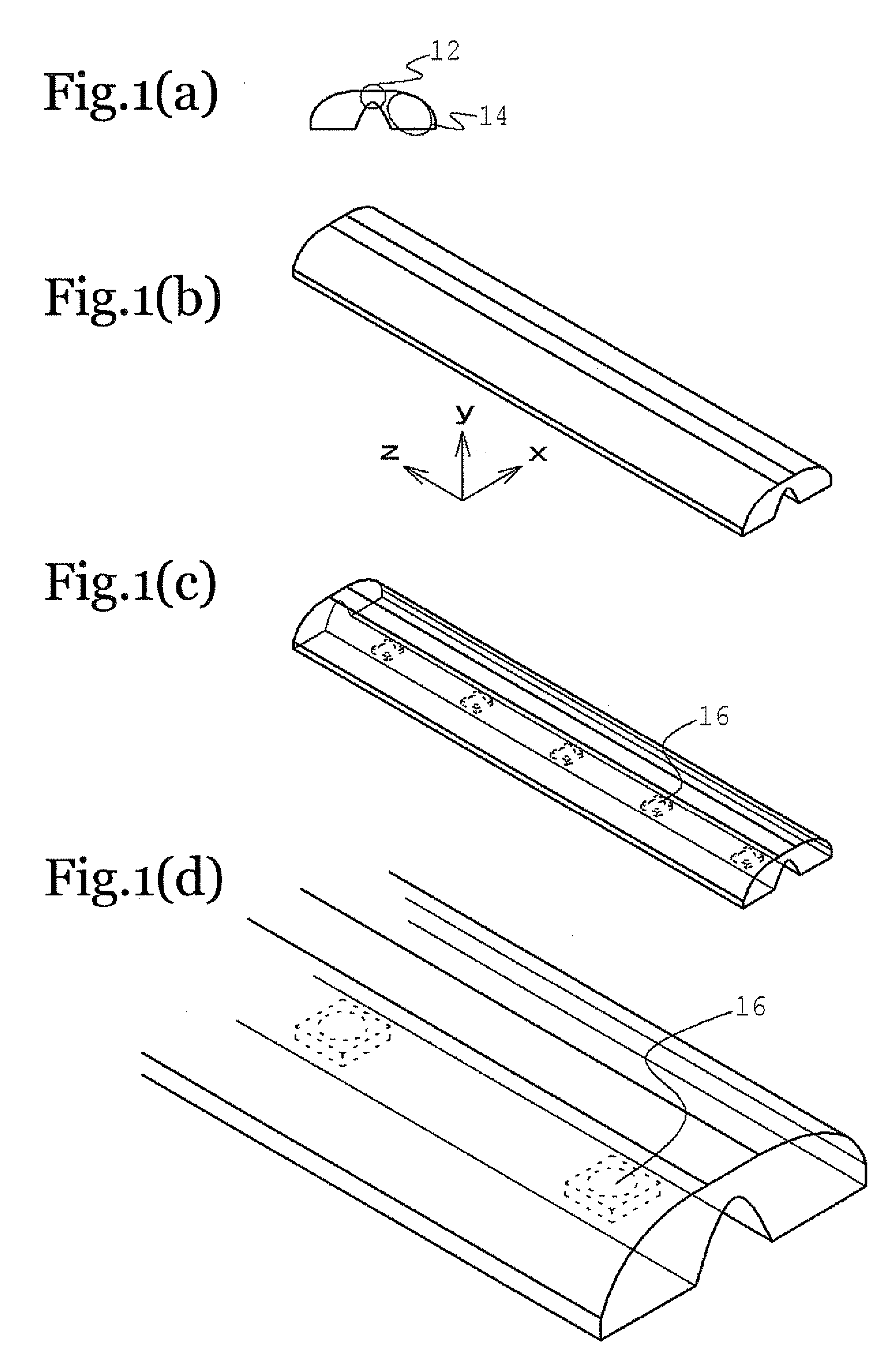
[0073] In this working example, as shown in FIG. 12, an image display device is equipped with a backlight light source involving a planar light source that is a combination of a cylindrical lens of the type shown in FIG. 1 and a light emitting diode having Lambertian light distribution characteristics.

[0074] This is a structure in which a metal heat sink is used as a supporting substrate to improve heat dissipation and increase the amount of current flowing into the light emitting diode.

[0075] The planar light sources of the present invention are disposed on this metal heat sink, which is used to diffuse heat from the light emitting diode and radiate it to the outside, at a suitable spacing determined by the light distribution characteristics and the distance between the light sources and the illuminated surface, which affords a light source device having a uniform illumination distribution, in which no bright spots, dark lines, or the like is seen in the illuminated surface.

[007...

working example 2

[0079] As shown in FIG. 13, this working example constitutes a planar lighting apparatus for a display refrigerator installed in a convenience store or the like and equipped with a planar light source.

[0080] The refrigerator was 1600 mm tall, the space between the columns at the ends of the glass doors was 762 mm (30 inches), planar light sources were laid out on the back of the columns in a row equal in length to the height of the refrigerator and facing the illuminated surface, and the distance between the light source and the surface of the displayed merchandise (the illuminated surface) was 177.8 mm (7 inches).

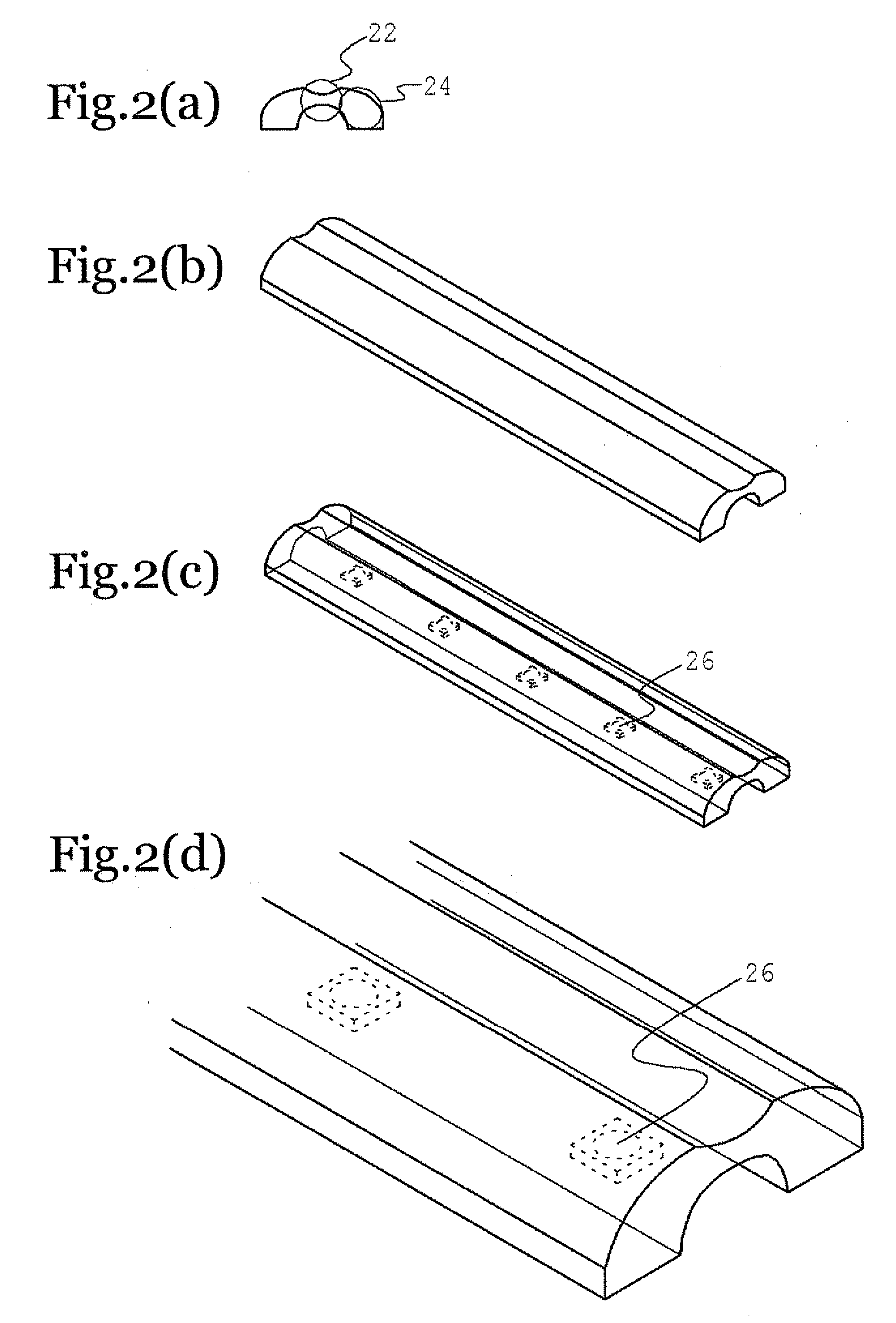
[0081] The cylindrical lens used here was injection molded from an acrylic resin, and measured 19.26 mm in the x direction, 6.1 mm in the y direction, and 400 mm in the z direction. The thickness in the x direction (the thickness of the convex lens) was 10 mm, and the thickness in the y direction (the thickness of the concave lens) was 2 mm. The structure used here cover...

working example 3

[0087] Working Example 3 is a light source apparatus used for passage illumination, and installed on the ceiling of an underground passageway in a dam or the like. In a location such as this, outside light is completely blocked off, and the walkway is only wide enough to allow workers to walk through in single file, so illumination that is adequate for moving about and working is obtained with just the brightness of a light emitting diode. In addition, since maintenance is more difficult in such locations, the long service life of light emitting diodes is especially valuable. Because of the unique functions produced by the light distribution characteristics of the present invention, not only the floor, but also the side walls of the passage can be brightly illuminated, which means that this lighting apparatus affords more than enough illumination for safe movement and for inspection and repair work.

[0088] The present invention can be applied to various kinds of lighting, such as ba...


PUM


Abstract

A planar light source comprises at least one point light source disposed on a supporting substrate, and a cylindrical lens that covers the light emitting observation side of the point light source, wherein the cylindrical lens has a concave lens function in the direction (y direction) perpendicular to the supporting substrate, and has a convex lens function in at least part of the horizontal direction (x direction).

Description

BACKGROUND OF THE INVENTION [0001] 1. Field of the Invention [0002] The present invention relates to a planar light source and a planar lighting apparatus, and more particularly relates to a planar light source used in backlight light sources for liquid crystal display devices used in channel letters and in image displays such as television sets, word processors, and computers. [0003] 2. Background Information [0004] Liquid crystal display devices having a backlight light source are beginning to be used in portable electronic devices and various kinds of image display devices. A liquid crystal display device is usually made up of a light-guide plate, a liquid crystal cell, a prism sheet, a diffuser, a backlight light source, and so forth (see Japanese Laid-Open Patent Application 2003-57622, for example). However, as the display devices used in liquid crystal displays have become larger in size, we are beginning to see the development of liquid crystal displays which do not make use...

Claims


Application Information

Patent Timeline
Patent Type & Authority Applications(United States)
IPC IPC(8): F21S6/00
CPCA47F3/001F21V5/04G02B3/06G09F13/22H01L33/58F21V5/10G02B19/0014G02B19/0061
Inventor MIYAIRI, HIROSHIWATANABE, KAZUNORI
Owner NICHIA CORP
Why Eureka
Try Eureka