Back Light Apparatus and Liquid Crystal Display Apparatus

a liquid crystal display and back light technology, applied in the direction of optical radiation measurement, instruments, measurement devices, etc., can solve the problems of large number of parts, difficult to view difficulty in viewing the liquid crystal display apparatus, so as to reduce structural restrictions, improve the effect of luminance and low cos

Inactive Publication Date: 2009-12-03
FUNAI ELECTRIC CO LTD
View PDF5 Cites 6 Cited by
  • Summary
  • Abstract
  • Description
  • Claims
  • Application Information

AI Technical Summary

Benefits of technology

[0012]The present invention is directed to provide a back light apparatus capable of emitting lights having more suitable luminance according to a surroundin

Problems solved by technology

For example, at a bright place, such as an exterior of a house, it is difficult to view the liquid crystal display apparatus if the display luminance thereof is not heightened.
On the contrary, at a dark place, such as an interior of a room, it is difficult to view the liquid crystal display apparatus if the display luminance thereof is not lowered.
However, because the technique disclosed in Japanese Patent Application Laid-Open Publication No. 2007-140260 arranges a sensor to each pixel, the number of parts becomes large.
Then, the technique has the problems of causing a rise in cost and making the control of the display apparatus more complicated.
As a result, as

Method used


Image

  • Back Light Apparatus and Liquid Crystal Display Apparatus
  • Back Light Apparatus and Liquid Crystal Display Apparatus
  • Back Light Apparatus and Liquid Crystal Display Apparatus

Examples


embodiment 1

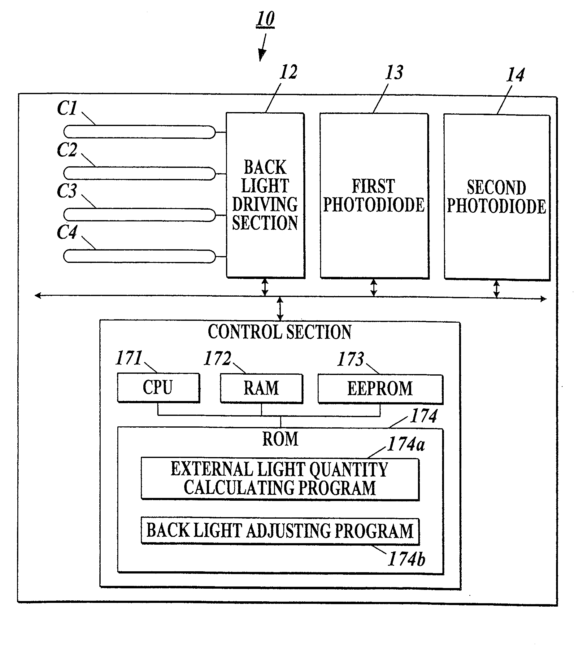
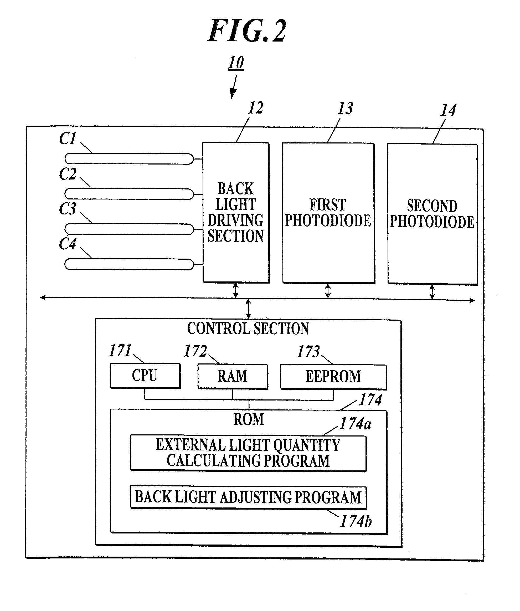
[0030]First, a liquid crystal display apparatus 100 of an embodiment 1, to which the present invention is applied, will be described.

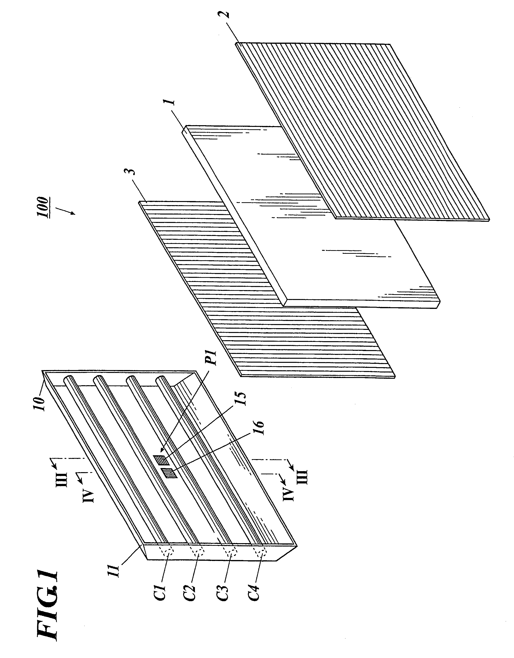
[0031]As shown in FIGS. 1-4, the liquid crystal display apparatus 100 of the present embodiment 1 is provided with a liquid crystal panel 1 and a back light apparatus 10 provided onto a back surface side of the liquid crystal panel 1 to radiate lights from the back surface side.

[0032]The liquid crystal panel 1 includes, for example, a pair of substrates provided at a predetermined interval, and a liquid crystal enclosed between the substrates. The liquid crystal is arranged to be twisted by, for example, 90 degrees in a no voltage applied state.

[0033]The liquid crystal panel 1 is put between two polarizing plates 2 and 3, the polarizing axes of which are perpendicular to each other. These polarizing plates 2 and 3 transmit only a light component having a vibration plane parallel to the polarizing axes of the polarizing plates 2 and 3, respectively, amo...

embodiment 2

[0065]Next, a liquid crystal display apparatus 200 of an embodiment 2, to which the present invention is applied, will be described.

[0066]Incidentally, in the following description, the similar components to those of the embodiment 1 are denoted by the same referential marks as those of the similar components of the embodiment 1, and their descriptions will be omitted.

[0067]As shown in FIGS. 7 and 8, the liquid crystal display apparatus 200 of the present embodiment 2 includes the liquid crystal panel 1 and a back light apparatus 20 provided on the back surface side of the liquid crystal panel 1 and radiating lights from the back surface side.

[0068]The first photodiodes 13 as the first light quantity detecting sections and the second photodiodes 14 as the second light quantity detecting sections are provided close to each other at respective predetermined positions of the housing 11, that is, at almost the central part P1, a position P2 near to the left end in a first space between ...

embodiment 3

[0085]Next, a liquid crystal display apparatus 300 of an embodiment 3, to which the present invention is applied, will be described.

[0086]Incidentally, in the following description, the similar components to those of the embodiment 1 or 2 are denoted by the same referential marks as those of the similar components of the embodiment 1 or 2, and their descriptions will be omitted.

[0087]As shown in FIGS. 9 and 10, the liquid crystal display apparatus 300 of the present embodiment 3 includes the liquid crystal panel 1 and a back light apparatus 30 provided on the back surface side of the liquid crystal panel 1 and radiating lights from the back surface side.

[0088]A back light driving section 31 adjusts the luminance of the four back light sources C1-C4 individually by applying alternating voltages to the four back light sources C1-C4 with inverters (not shown) provided correspondingly to the four back light sources C1-C4, respectively.

[0089]The first photodiode 13 as the first light qua...


PUM


Abstract

A back light apparatus includes an external light quantity detecting unit having a first and second light quantity detecting sections, both of which are provided at a predetermined position of the housing, a first polarizing plate provided on a light receiving surface of the first light quantity detecting section, which first polarizing plate has a polarizing axis perpendicular to that of a polarizing plate provided on the rear surface side of the liquid crystal panel, a second polarizing plate provided on the light receiving surface of the second light quantity detecting section, which second polarizing plate has the same polarizing axis as that of the polarizing plate provided on the rear surface side of the liquid crystal panel, and an external light quantity calculating section to calculate the external light quantity based on the difference value between light quantities detected by the first and second light quantity detecting sections.

Description

BACKGROUND OF THE INVENTION[0001]1. Field of the Invention[0002]The present invention relates to a back light apparatus to be used as a light source of a liquid crystal display panel, and a liquid crystal display apparatus equipped with the back light apparatus.[0003]2. Description of Related Art[0004]A liquid crystal display apparatus performs an image display by controlling an orientation of a liquid crystal put between two electrodes in a liquid crystal display panel to pass or intercept the lights from back lights.[0005]Such a liquid crystal display apparatus has a characteristic in which the visibility of a display image changes according to surrounding brightness. For example, at a bright place, such as an exterior of a house, it is difficult to view the liquid crystal display apparatus if the display luminance thereof is not heightened. On the contrary, at a dark place, such as an interior of a room, it is difficult to view the liquid crystal display apparatus if the display ...

Claims


Application Information

Patent Timeline
IPC IPC(8): G09G3/36
CPCG01J1/4204G01J1/4228G09G2360/144G09G3/342G02F1/133602
Inventor YAMASHITA, HIROSHIYAMANAKA, YUSAKU
Owner FUNAI ELECTRIC CO LTD
Why Eureka
Try Eureka