Method and apparatus for cutting a workpiece

a technology for cutting workpieces and cutting tools, applied in the field of methods and equipment, can solve the problems of difficult to cope with cuts, difficult to cut, and most difficult construction projects for most people to finish carpentry

Inactive Publication Date: 2006-09-14
BLACK & DECKER INC
View PDF23 Cites 37 Cited by
  • Summary
  • Abstract
  • Description
  • Claims
  • Application Information

AI Technical Summary

Benefits of technology

[0037]FIG. 23 is fragmentary front side elevational view of an alternate embodiment of a scanner of the present invention with a portion of the housing cut away for clarity.

Problems solved by technology

One of the most difficult construction projects for most people is finish carpentry.
While most people can readily learn how to cut miter cuts for making miter joints, miter cuts do not always create the best joint.
Unfortunately, cope cuts are difficult to make and require a high skill level to accomplish using traditional methods.
In addition to requiring more skill, cope cuts are more labor intensive and take more time to make using traditional methods than a simple miter cut.
This often leads to imprecise cuts and errors in all but those cuts performed by the most skilled craftsman and, occasionally, to unusable cuts resulting in wasted time and materials.
A drawback of this device is the necessity of a template for each type of molding the user desires to cut.
While this device would reduce fatigue over the conventional hand saw method, this device still, however, requires the operator to have the skill necessary to cut out the profile free hand, thus leading to errors.
While this device represents an improvement over the prior art in that it holds the cutting apparatus securely, the craftsman must still create the cut free hand, thereby leading to errors, wasted time and wasted material.

Method used


Image

  • Method and apparatus for cutting a workpiece
  • Method and apparatus for cutting a workpiece
  • Method and apparatus for cutting a workpiece

Examples


second embodiment

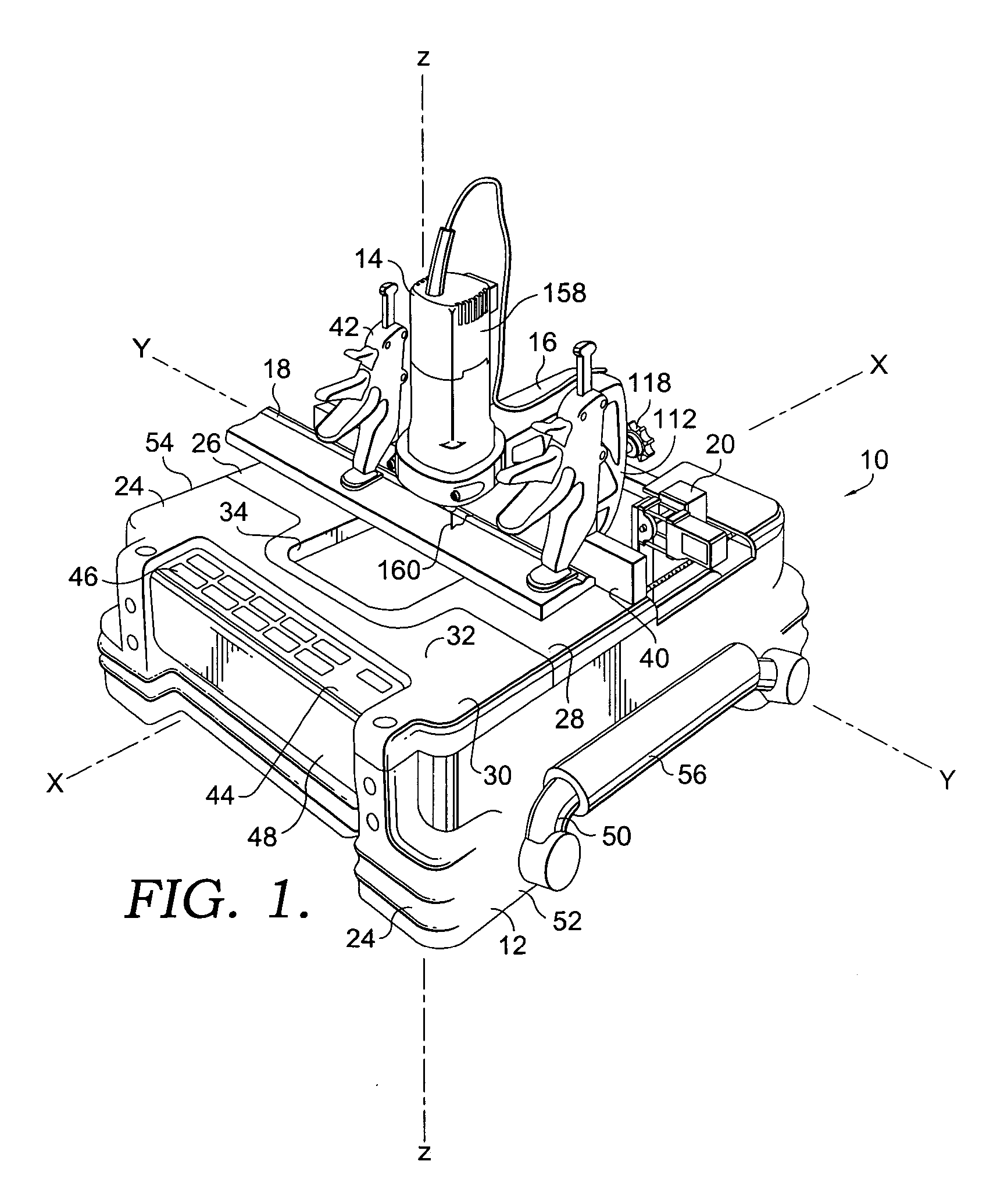
[0092] For example, FIGS. 16 and 17 illustrate an alternate or second embodiment of a cutting apparatus 10′ of the present invention. Because the cutting apparatus 10′ of this alternate embodiment includes many of the same elements as discussed above, the elements of the alternate embodiment will be referenced by the numerals given above in connection with the above discussed embodiment. However, in the event that an element of the alternate embodiment is modified from the corresponding element of the previous embodiment, the reference numeral will be followed by a prime mark.

[0093] The apparatus 10′ is illustrated in FIGS. 16 and 17 with the housing 24′ removed. Alternatively, the apparatus 10′ could be used without the housing and as substantially illustrated. The apparatus 10′ includes modified hold downs or clamps 42′. The clamps 42′ of this alternate embodiment have been designed to provide a lower profile than the clamps 42 previously disclosed so that they do not interfere wi...

first embodiment

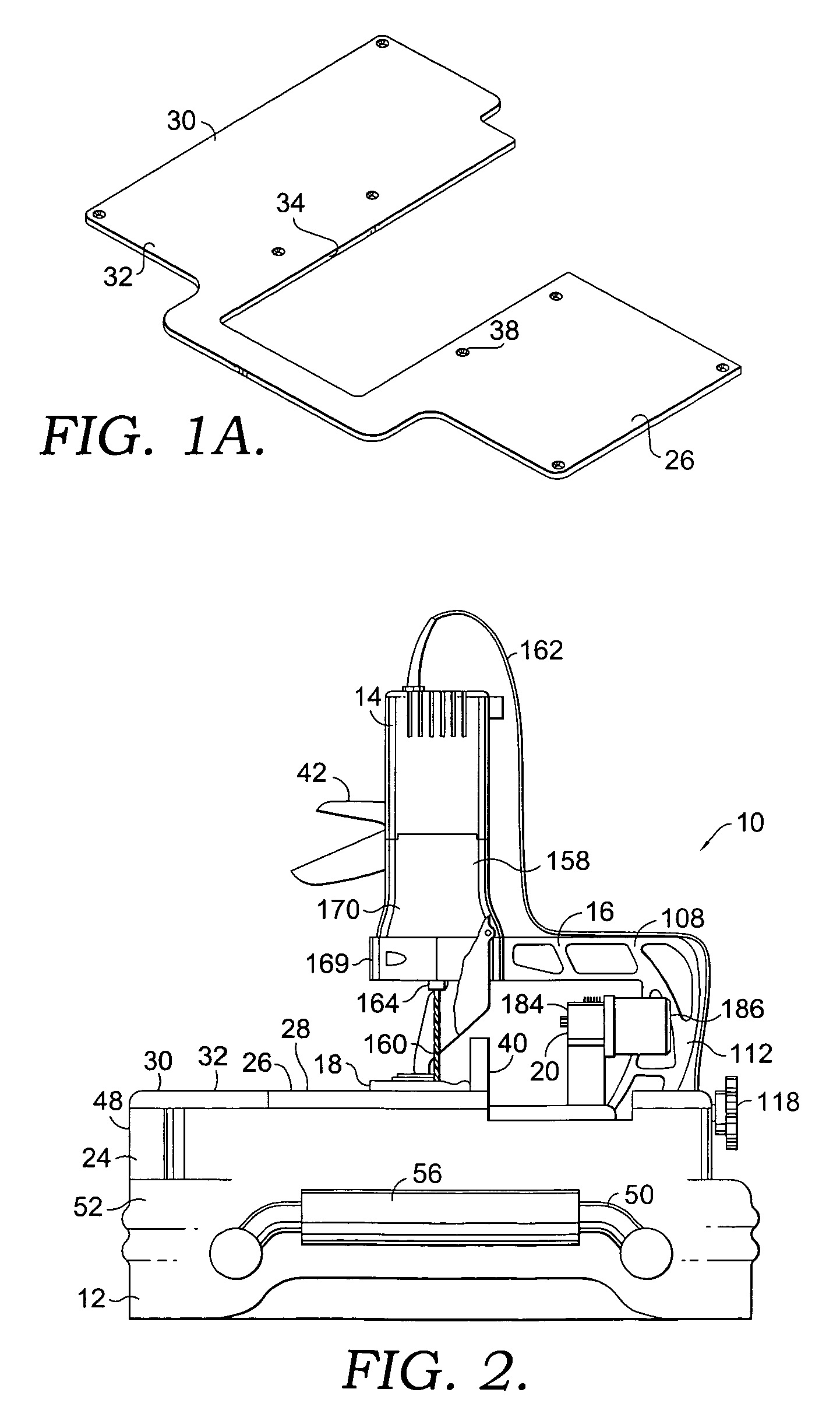
[0104]FIG. 18 also illustrates an alternate embodiment of the lower collet 166, as best viewed in FIG. 18A. In the apparatus 10, the upper and lower collets 164, 166 were standard collets that require wrenches to tighten. While that arrangement certainly works, the positioning of the lower collet 166 below the work surface 32 limits access to the lower collet 166 and can make the use of wrenches for tightening the lower the collet 166 difficult. Accordingly, FIGS. 18 and 18A disclose a tool-less pushbutton collet 382 which replaces the lower collet 166 described above. As discussed above, when the cutting blade 160 is a double shank rotating cutting blade 160, it is held on both ends by collets. The upper collet 164 is integral to the motor drive and thus transmits torque from the motor 158 to the cutting blade 160 while also holding and defining the cutting blade's axis of rotation. The lower collet 166, 282 defines the same axis of rotation while also providing needed radial suppo...


PUM


Abstract

An apparatus for obtaining a desired cut in a workpiece and a method of using the same is provided. The apparatus has a base with a cutting member moveably coupled thereto. A scanner is coupled with the base for scanning the profile of the workpiece desired to be cut. A computing device may use information from the scanning process to control transverse and longitudinal stepper motors to move the cutting member through a desired cutting path to achieve a cut based on the profile of the workpiece, such as a cope cut. A user can store profiles of previously scanned workpieces in a memory component of the computing device.

Description

CROSS-REFERENCE TO RELATED APPLICATIONS [0001] Not applicable. STATEMENT REGARDING FEDERALLY SPONSORED RESEARCH OR DEVELOPMENT [0002] Not applicable. BACKGROUND OF THE INVENTION [0003] The present invention relates to a method and apparatus for obtaining a desired cut in a workpiece. More particularly, this invention relates to a cutting apparatus having a base, a scanner coupled with the base for determining the profile of a workpiece, a cutting member selectively movable with respect to the base as a result of information obtained from the user and / or the scanning process, and a computing device for controlling movement of the cutting apparatus during use. [0004] One of the most difficult construction projects for most people is finish carpentry. While most people can readily learn how to cut miter cuts for making miter joints, miter cuts do not always create the best joint. For example, while a miter joint might be the preferred joint for framing the casing around a door or windo...

Claims


Application Information

Patent Timeline
Patent Type & Authority Applications(United States)
IPC IPC(8): G06F19/00
CPCB23Q35/128G05B2219/36248
Inventor CARPENTER, DAVID ALANPUZIO, DANIELO'BANION, MICHAEL L.
Owner BLACK & DECKER INC
Why Eureka
Try Eureka