Load carrier foot

a technology for loading carriers and rail profiles, applied in transportation and packaging, vehicle components, supplementary fittings, etc., can solve problems such as unsafe connection of load carriers to rail profiles, failure of locking devices to be properly engaged, and possible determination

Inactive Publication Date: 2006-09-21
THULE SWEDEN AB
View PDF8 Cites 21 Cited by
  • Summary
  • Abstract
  • Description
  • Claims
  • Application Information

AI Technical Summary

Benefits of technology

[0004] One object of the present invention is to provide a load carrier foot which includes a connection part that is firmly secured to the locking device and rotatably connected to the base part, and a resilient member that is located between the base part and the connection part, which rotates the connection part and the locking device

Problems solved by technology

The disadvantage with these previously-known load carrier feet is that the locking device can fail to be properly engaged when being fastened against the walls, whereby an unsafe connection of the load carrier foot to the rail profile is created.
When the locking device is located within the cavity it may not be possible

Method used


Image

  • Load carrier foot
  • Load carrier foot
  • Load carrier foot

Examples


Embodiment Construction

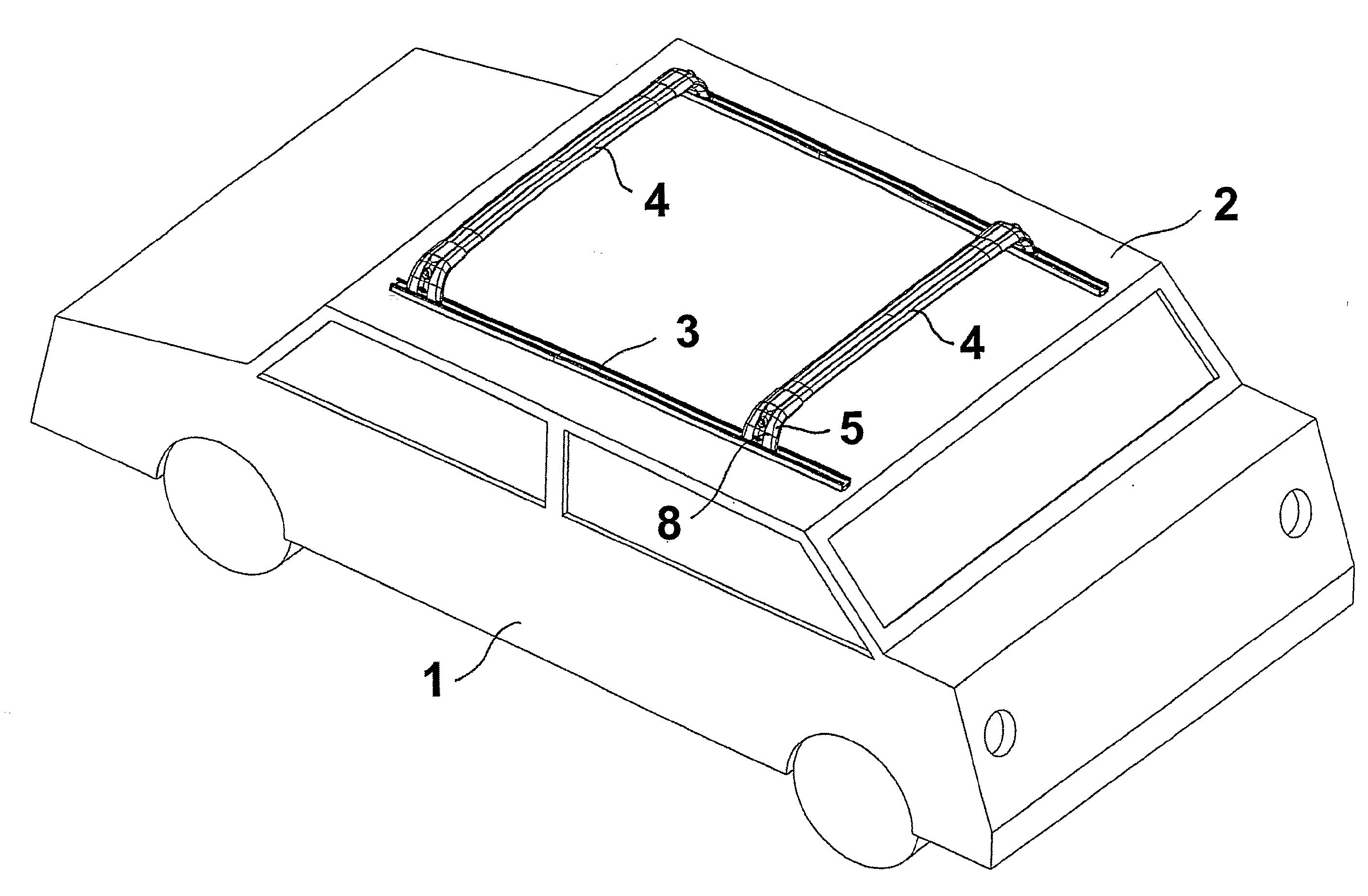
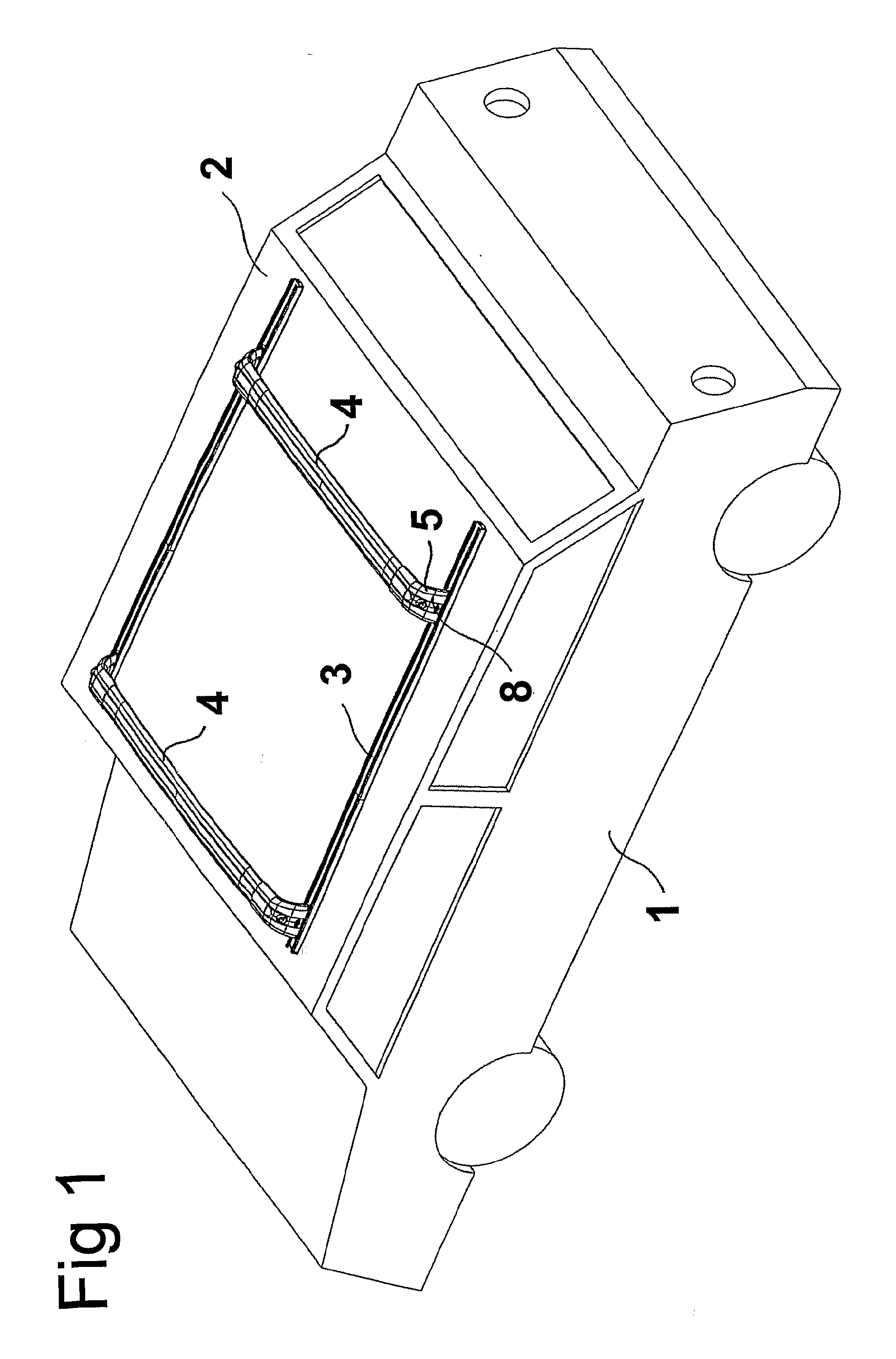
[0020] With reference to FIG. 1, vehicle 1 is shown with elongated rail profiles 3 connected to roof 2, and to which load carrier rods 4 provided with load carrier feet 5 according to an embodiment of the present invention are mounted.

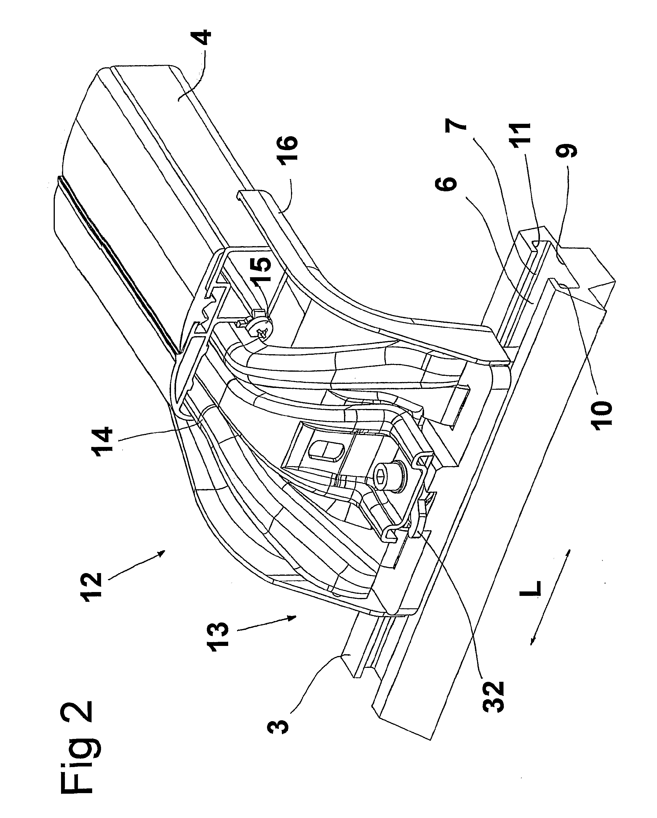
[0021]FIG. 2 discloses a portion of rail profile 3, which longitudinal direction has been indicated with the double arrow “L” and to which load carrier foot 5 is mounted. The rail profile has cavity 6, with an upwards-turned opening 7, and in FIG. 3 the width of the cavity is indicated by “B” and the width of the opening by “b”. As shown in the figure the width of the cavities is larger than the width of the opening. Cover 8 which covers the inner part of the foot and which is shown in FIG. 1, a function of which is to provide an attractive exterior, is omitted in the figure. Bottom 9 of cavity 6 is shown and the walls of the cavity, located adjacent to the opening, designated 10 and 11 respectively, and as shown, are directed essentially downwards ag...


PUM


Abstract

Load carrier foot (5) for connecting a load carrier bar (4) to an, at a vehicle connected, elongated rail profile (3), having in the longitudinal direction (L) of the rail an extended cavity (6), with an upwards turned opening (7), in which the width (B) of the cavity across the longitudinal direction of the rail exceeding the width (b) of the opening, whereby the cavity on each side of the opening having walls (10, 11), which are directed essentially downwards against the bottom (9) of the cavity, whereby the load carrier foot having a base part (13), which extends through the opening towards the bottom of the cavity. A fastening device (29), which by means of a clamping device (51) is moved upwards to clamping contact with the downwards directed walls (10, 11) when the base part being secured to the rail profile. A connection means (25,30) is firmly connected with the locking device (29) and turnable connected to the base part (13), and an elastic body (24) is located between the base part and the connection means, which turns the connection means and the locking device to a position in which the locking device being located transverse relative the longitudinal direction of the rail profile when the base part is mounted to the cavity, and in which position the locking device certainly will be in contact with the downwards directed walls (10, 11) when the locking device being clamped against the walls by the clamping device (51).

Description

TECHNICAL FIELD OF THE INVENTION [0001] The present invention relates to a load carrier foot for connecting a load carrier bar to a vehicle with an elongated rail profile, having in the longitudinal direction of the rail an extending cavity, with an upwards-turned opening, in which the width of the cavity across the longitudinal direction of the rail exceeds the width of the opening, whereby the cavity on each side of the opening includes walls, which are directed essentially downwards against the bottom of the cavity, wherein the load carrier foot having a base part, which extends through the opening towards the bottom of the cavity and comprising a fastening device, which by a clamping device is moved upwards to a clamping connection with the downwards-directed walls when the base part is secured to the rail profile. BACKGROUND OF THE INVENTION [0002] Load carrier feet are previously known. The disadvantage with these previously-known load carrier feet is that the locking device c...

Claims


Application Information

Patent Timeline
IPC IPC(8): B60R9/00B60R9/045
CPCB60R9/045
Inventor KARLSSON, PETER
Owner THULE SWEDEN AB
Why Eureka
Try Eureka