Positioning device for movable crossbeam and main unit framework of horizontal tensile tester

A horizontal tensile test, moving beam technology, applied in the direction of measuring devices, instruments, scientific instruments, etc., can solve problems such as insecurity, increase equipment manufacturing costs, increase lifting equipment, etc., achieve rapid positioning and release positioning, and improve work efficiency , the effect of convenient operation

Active Publication Date: 2012-06-27
JINAN SHIJIN GROUP
View PDF4 Cites 1 Cited by
  • Summary
  • Abstract
  • Description
  • Claims
  • Application Information

AI Technical Summary

Problems solved by technology

[0003] However, this above-mentioned positioning method requires the tester to directly insert the positioning pin into the positioning hole, which has operational difficulties and unsafe factors. Especially when the positioning pin itself is heavy, it is necessary to increase the lifting equipment and increase the capital investment of the test equipment.
It should be pointed out that the above positioning method requires the end of the moving beam to be accommodated in the recessed receiving part of the main frame, correspondingly increasing the length of the moving beam and the height of the wings of the main frame, increasing the manufacturing cost of the equipment

Method used


Image

  • Positioning device for movable crossbeam and main unit framework of horizontal tensile tester
  • Positioning device for movable crossbeam and main unit framework of horizontal tensile tester
  • Positioning device for movable crossbeam and main unit framework of horizontal tensile tester

Examples


Embodiment Construction

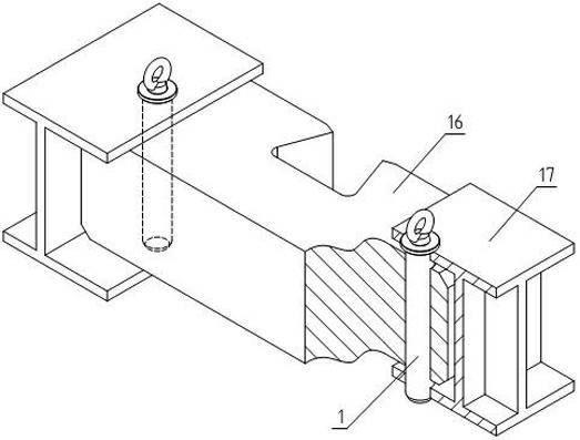
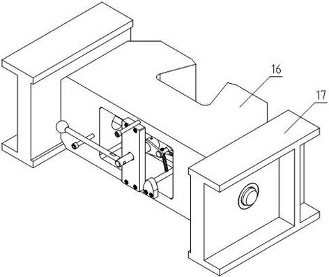
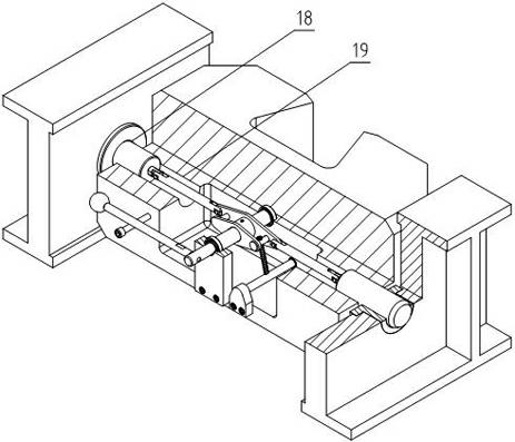
[0021] Such as Figure 2-4 As shown, a horizontal tensile testing machine is a positioning device for the moving beam and the main frame, the middle part of the moving beam 16 has accommodating space, and the two ends of the moving beam and the corresponding side waists of the main frame 17 are provided with matching horizontal positioning holes ( 18 and 19), the positioning holes at both ends of the moving beam communicate with the accommodating space, and a rotating shaft 13 perpendicular to the direction of the positioning holes is erected in the accommodating space, and positioning pins 1 are respectively accommodated in the positioning holes, and each positioning pin faces the rotating shaft One end of each connecting rod is hinged to a connecting rod 2, and the other end of each connecting rod is respectively hinged to a member 4 fixed on the rotating shaft.

[0022] In the above positioning device, one end of the rotating shaft is installed on the bearing hole inside th...


PUM


Abstract

The invention provides a positioning device for a movable crossbeam and a main unit framework of a horizontal tensile tester, which is safe and convenient in operation. The middle of the movable crossbeam is provided with a containing space, each of two ends of the movable crossbeam and the waist on the corresponding side of the main unit framework are respectively provided with transverse positioning holes matched mutually, the positioning holes at two ends of the movable crossbeam are communicated with the containing space, and a rotary shaft perpendicular to directions of the positioning holes is erected in the containing space. Positioning pins are inserted in the positioning holes respectively, the end of each positioning pin facing the rotary shaft is hinged with a connecting rod, and the other end of each connecting rod is hinged to a component on the rotary shaft. Besides, hinged points on the component are located on two sides of the rotary shaft respectively, and the hinged point on each side is connected with a connecting rod on the corresponding side.

Description

technical field [0001] The invention relates to a positioning device for a movable beam and a main frame of a horizontal tensile testing machine. Background technique [0002] The horizontal tensile testing machine needs to adjust the position of the moving beam on the main frame to adapt to the test space required by the sample, such as figure 1 As shown, the two ends of the moving beam 16 of the horizontal tensile testing machine in the prior art are respectively accommodated in the recessed receiving parts on the opposite sides of the main frame 17, and the ends of the moving beam and the wings of the main frame are provided with common receiving positioning pins 1 The direction of the positioning hole is parallel to the waist of the main frame, so as to realize the stable positioning of the moving beam and the main frame. The above positioning method is widely used because of its simple structure and high reliability. [0003] However, this above-mentioned positioning ...

Claims


Application Information

Patent Timeline
Patent Type & Authority Applications(China)
IPC IPC(8): G01N3/02
Inventor 房文平乌慧霞郭海森
Owner JINAN SHIJIN GROUP
Why Eureka
Try Eureka