Eureka AIR delivers breakthrough ideas for toughest innovation challenges, trusted by R&D personnel around the world.

Toner supplying system for an image forming apparatus

Inactive Publication Date: 2006-09-21
RICOH KK
View PDF32 Cites 19 Cited by
  • Summary
  • Abstract
  • Description
  • Claims
  • Application Information

AI Technical Summary

Benefits of technology

[0009] It is an object of the present invention to overcome one or more of the above-identified or other disadvantages.
[0010] The present invention can provide an image forming apparatus including an image carrier configured to form a latent image. A developing unit includes a developer carrier configured to carry toner, and a toner conveying member arranged between the image carrier and the developer carrier, including a plurality of electrodes arranged at predetermined intervals. The toner conveying member is configured to receive and convey the toner carried by the developer carrier to a region at which the toner conveying member faces the image carrier as a result of a conveying electric field generated by a plurality of electrodes with an application of multi-phased voltages. A first potential application mechanism is configured to apply a first voltage to the developer carrier. A second potential application mechanism is configured to apply a second voltage to the toner conveying member such that a first electric field defined as a ratio of a first potential difference between the toner conveying member and the developer carrier to a distance between the toner conveying member and the developer carrier is less than a second electric field defined as a ratio of the second voltage of the second potential application mechanism to a space between two adjacent electrodes of the plurality of electrodes.
[0011] The present invention further can provide an image forming apparatus including means for carrying an image. A developing unit includes means for carrying toner, and means for receiving and conveying the toner carried by the means for carrying toner to a region at which the means for conveying faces the means for carrying an image as a result of a conveying electric field generated by a plurality of electrodes at predetermined intervals with an application of the multiple-phased voltages and arranged between the means for carrying an image and the means for carrying toner. First means are used for applying a first voltage to the means for carryin

Problems solved by technology

The developing speed is limited, however, by the amount of toner supplied to the toner transporting member.
If the toner cannot be conveyed due to an unsuitable voltage condition applied to the electrodes, the toner may adhere to the toner transporting member.
Moreover, the electric field generated on the toner transporting member also affects the toner supply to the toner transporting member.
This is a problem unique to the image forming apparatus that uses the traveling-wave electric field.
If the electric field on the toner transporting member prevents the toner from being supplied to the toner transporting member, the efficiency of the development degrades due to the lack of toner.

Method used


Image

  • Toner supplying system for an image forming apparatus
  • Toner supplying system for an image forming apparatus
  • Toner supplying system for an image forming apparatus

Examples


Embodiment Construction

[0044] In describing preferred embodiments illustrated in the drawings, predetermined terminology is employed for clarity. However, the following description is not intended to be limited to the predetermined terminology selected, and it is to be understood that described components includes all technical equivalents that operate in a similar manner.

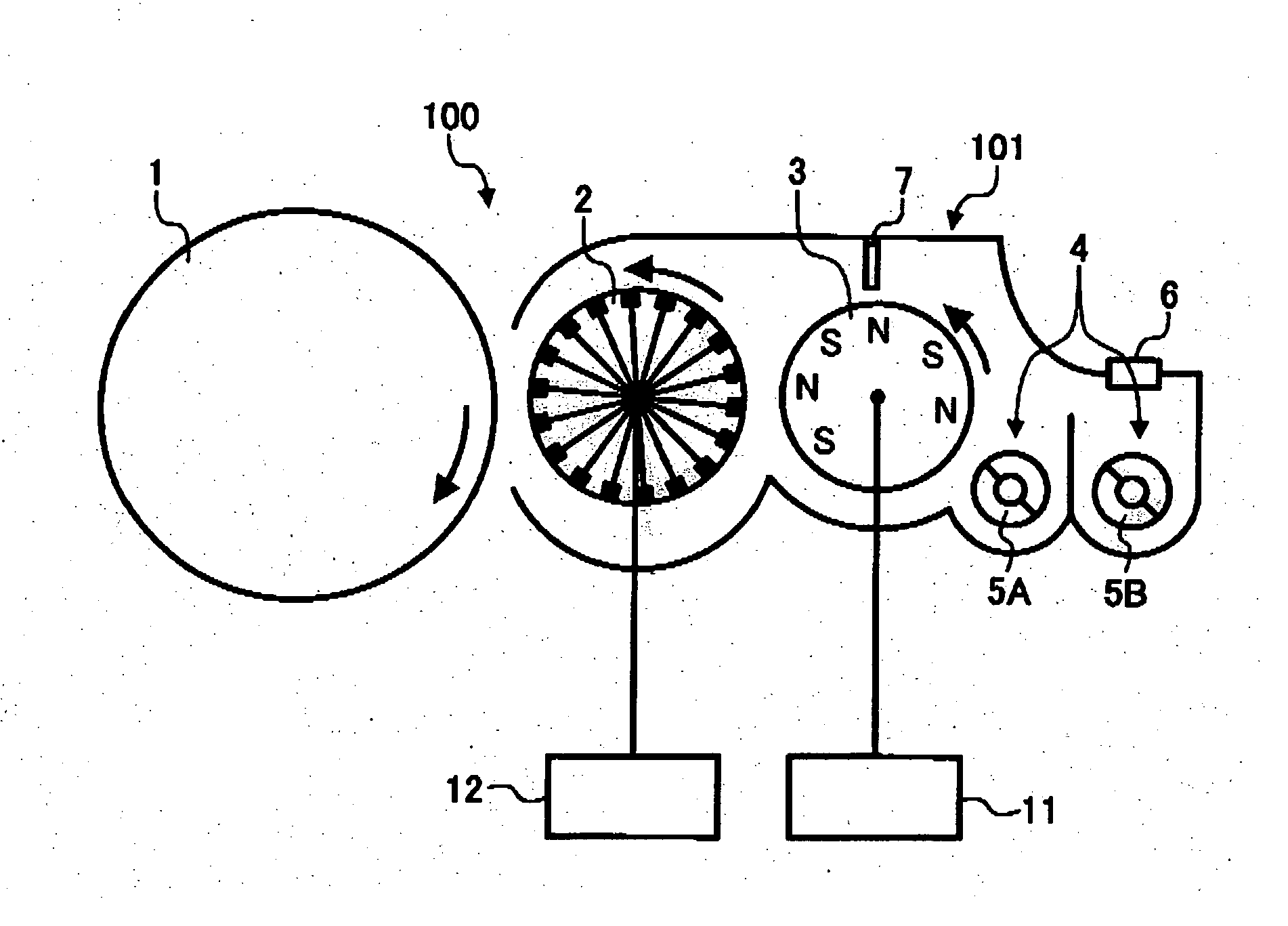
[0045] Referring now to the drawings, wherein like reference numerals designate identical or corresponding parts throughout the several views, FIG. 1 shows an image forming apparatus 100 according to an embodiment of the present invention.

[0046] As shown in FIG. 1, the image forming apparatus 100 includes an image carrier 1, a developing unit 101, and first- and second-potential application mechanisms 11 and 12, respectively. The developing unit 101 is a two-component developing system which utilizes a two-component developer including a magnetic carrier and a non-magnetic toner. The developing unit 101 includes a toner conveying membe...


PUM


Abstract

An image forming apparatus including an image carrier configured to have a latent image formed thereon, a developer carrier configured to supply toner, and a conveying member configured to receive toner from the developer carrier and to convey the toner to the image carrier. The conveying member includes first and second electrodes disposed a predetermined distance from one another. A first voltage application unit is configured to apply a first voltage to the developer carrier. A second voltage application unit is configured to apply a second voltage to the conveying member such that a ratio of a potential difference between the conveying member and the developer carrier to a distance between the conveying member and the developer carrier is less than a ratio of the second voltage to the predetermined distance.

Description

BACKGROUND OF THE INVENTION [0001] 1. Field of the Invention [0002] The present invention relates to an image forming apparatus, and more particularly to an image forming apparatus stably and efficiently supplying toner. [0003] 2. Discussion of the Related Art [0004] Known image forming apparatuses, such as printers, facsimiles, copiers, and multifunction apparatuses that print, fax and copy, generally use an electrophotographic process for image forming. The electrophotographic process includes a process of charging an image carrier, a latent image forming process, a developing process in which color powder (toner) is adhered, and a transferring process that transfers the toner image to a recording medium, such as paper. [0005] The known image forming apparatus includes an image carrier, a toner transporting member and a power supply. The toner is supplied to the toner transporting member using a magnetic brush, for example, and is then conveyed to the image carrier. The toner tran...

Claims


Application Information

Patent Timeline
IPC IPC(8): G03G15/08
CPCG03G15/0813G03G2215/0634
Inventor NAKAGAWA, YOSHINORIHORIKE, MASANORIMIYAGUCHI, Y.M. YOHICHIROHKONDOH, NOBUAKISAKAI, KATSUO
Owner RICOH KK
Why Eureka
Eureka Blog
Learn More