Eureka AIR delivers breakthrough ideas for toughest innovation challenges, trusted by R&D personnel around the world.

Image forming apparatus

Active Publication Date: 2006-09-21
RICOH KK
View PDF12 Cites 34 Cited by
  • Summary
  • Abstract
  • Description
  • Claims
  • Application Information

AI Technical Summary

Problems solved by technology

However, if the corotron is used, an amount of ozone emissions is large, which is problematic from a point of view of environmental protection.
Moreover, since there are tension rollers in the front and in the rear of a transfer point, a size and cost of the apparatus increase.
Even if a transfer roller is arranged an at a downstream side to the photosensitive element to improve transfer performance, it is disadvantageous since there is a tension roller at a further downstream side to the transfer roller, a size and cost of the apparatus increases.
However, there is no description of an effect on transfer performance itself.

Method used


Image

  • Image forming apparatus
  • Image forming apparatus
  • Image forming apparatus

Examples


Embodiment Construction

[0015] Exemplary embodiments according to the present invention will be explained in detail below with reference to the accompanying drawings. In the explanation, although detailed designations of members are used for ease in understanding the invention, these designations by no means limit the scope of applicability of the invention.

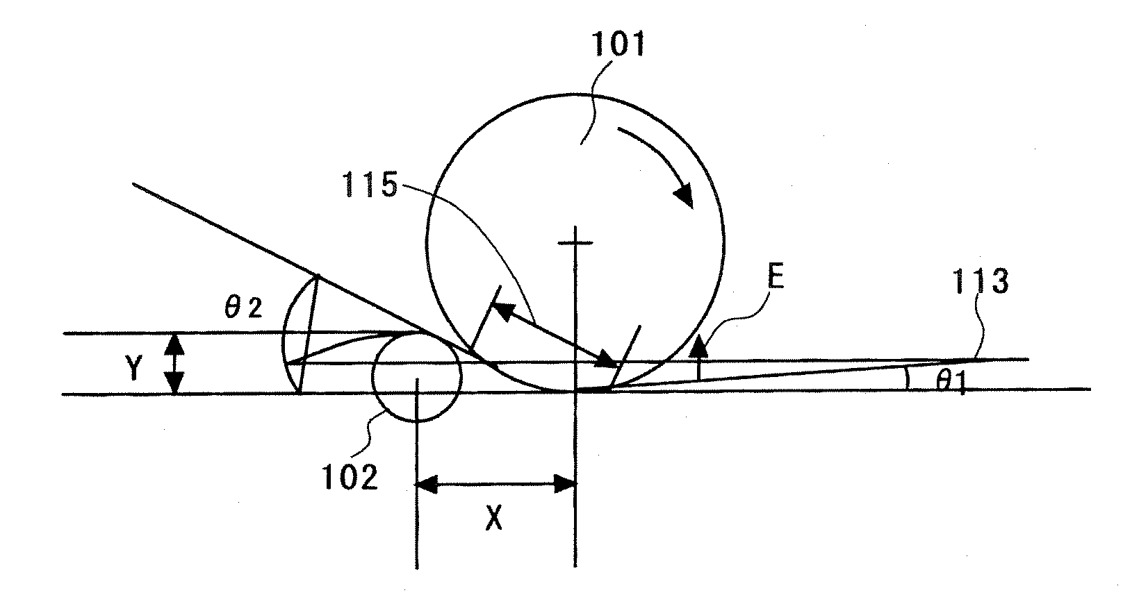
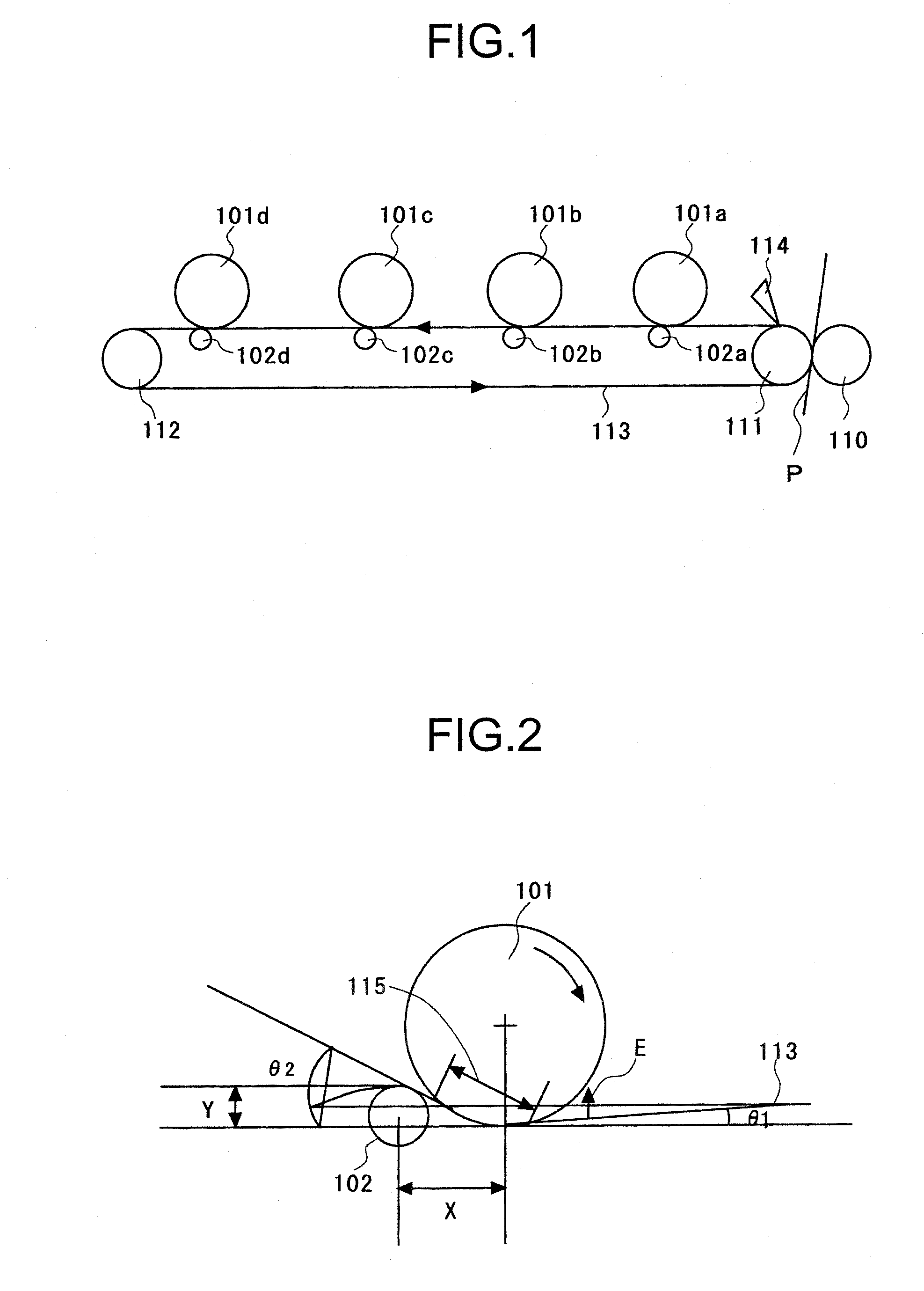
[0016]FIG. 1 is a schematic of an image forming apparatus according to an embodiment of the present invention including a transfer unit. The image forming apparatus includes an image carrier 101 and a primary transfer roller 102 that is disposed on an intermediate transfer belt 113 formed in an endless belt. The image carrier 101 includes four image carriers 101a to 101d, and the primary transfer roller 102 includes four metallic rollers 102a to 102d. The primary transfer roller 102 includes metallic rollers and configured to form a color image on the intermediate transfer belt (transfer belt) 113.

[0017] As shown in FIG. 1, the intermediate transfer b...


PUM


Abstract

A primary transfer unit includes transfer units for performing a toner transfer from image carriers onto a transfer belt. Each of the transfer units is formed with a metallic roller. The metallic roller is arranged so as to satisfy θ1<θ2, where an angle of the endless belt with respect to a tangent to the image carrier, on a side upstream of rotation of the endless belt to a transfer nip region where the image carrier and the endless belt are in contact is θ1, and an angle of the endless belt with respect to the tangent, on a side downstream of rotation of the endless belt to the transfer nip region is θ2.

Description

CROSS-REFERENCE TO RELATED APPLICATIONS [0001] The present document incorporates by reference the entire contents of Japanese priority document, 2005-080713 filed in Japan on Mar. 18, 2005. BACKGROUND OF THE INVENTION [0002] 1. Field of the Invention [0003] The present invention relates to an image forming apparatus using electrophotography. [0004] 2. Description of the Related Art [0005] For color image forming apparatuses, techniques for reducing hollow defects of characters and thin lines caused at a primary transfer unit have been developed. In a technique disclosed in Japanese Patent Application Laid-Open No. H10-10876, an entrance / exit angle of a belt of a primary transfer unit is differed at an upstream side and a downstream side of rotation. When the transfer unit is a corotron, the transfer unit is arranged not to contact a photosensitive element, and the belt is arranged to make contact with the photosensitive element by applying tension. Because toner transfer is carried ...

Claims


Application Information

Patent Timeline
IPC IPC(8): G03G15/16
CPCG03G15/0131G03G2215/0119G03G2215/0132
Inventor IWAKURA, YOSHIEKAWASAKI, AKIHIROTAKEHARA, ATSUSHIMIYAZAKI, TAKAFUMIADACHI, TOMOYA
Owner RICOH KK
Why Eureka
Eureka Blog
Learn More