Eureka AIR delivers breakthrough ideas for toughest innovation challenges, trusted by R&D personnel around the world.

Substrate incorporating non-woven elements

a non-woven element and substrate technology, applied in the field of textile substrates, can solve the problems of short circuit, elongated items such as wiring harnesses, and may endure harsh environmental conditions

Inactive Publication Date: 2006-09-28
FEDERAL MOGUL WORLD WIDE
View PDF32 Cites 35 Cited by
  • Summary
  • Abstract
  • Description
  • Claims
  • Application Information

AI Technical Summary

Benefits of technology

"The invention is a substrate that includes two sets of filamentary members and non-woven material. The first set of filamentary members is oriented in one direction and spaced apart from each other, while the second set of filamentary members is oriented in a perpendicular direction and also spaced apart from each other. The second set of filamentary members interlaces with the first set to create an open mesh. The non-woven material is positioned between the first set of filamentary members and interlaced with the second set. This design provides a substrate that has improved strength and flexibility."

Problems solved by technology

Elongated items, such as wiring harnesses for example, may endure harsh environmental conditions in automotive, aerospace and marine applications.
For example, wiring harnesses may be subjected to vibrations during vehicle operation which can cause abrasion of electrical insulation and result in short circuits.
The harnesses may also be exposed to extreme high temperatures due to incident radiant heat, particularly in engine compartments.
Furthermore, the harnesses may be subjected to radio frequency or electromagnetic interference or may be the source of such interference.
Consideration of radio frequency interference is of particular concern when the wiring harnesses are carrying control signals or emit interference which interferes with radio reception.

Method used


Image

  • Substrate incorporating non-woven elements
  • Substrate incorporating non-woven elements
  • Substrate incorporating non-woven elements

Examples


Embodiment Construction

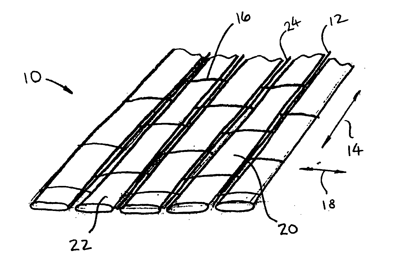
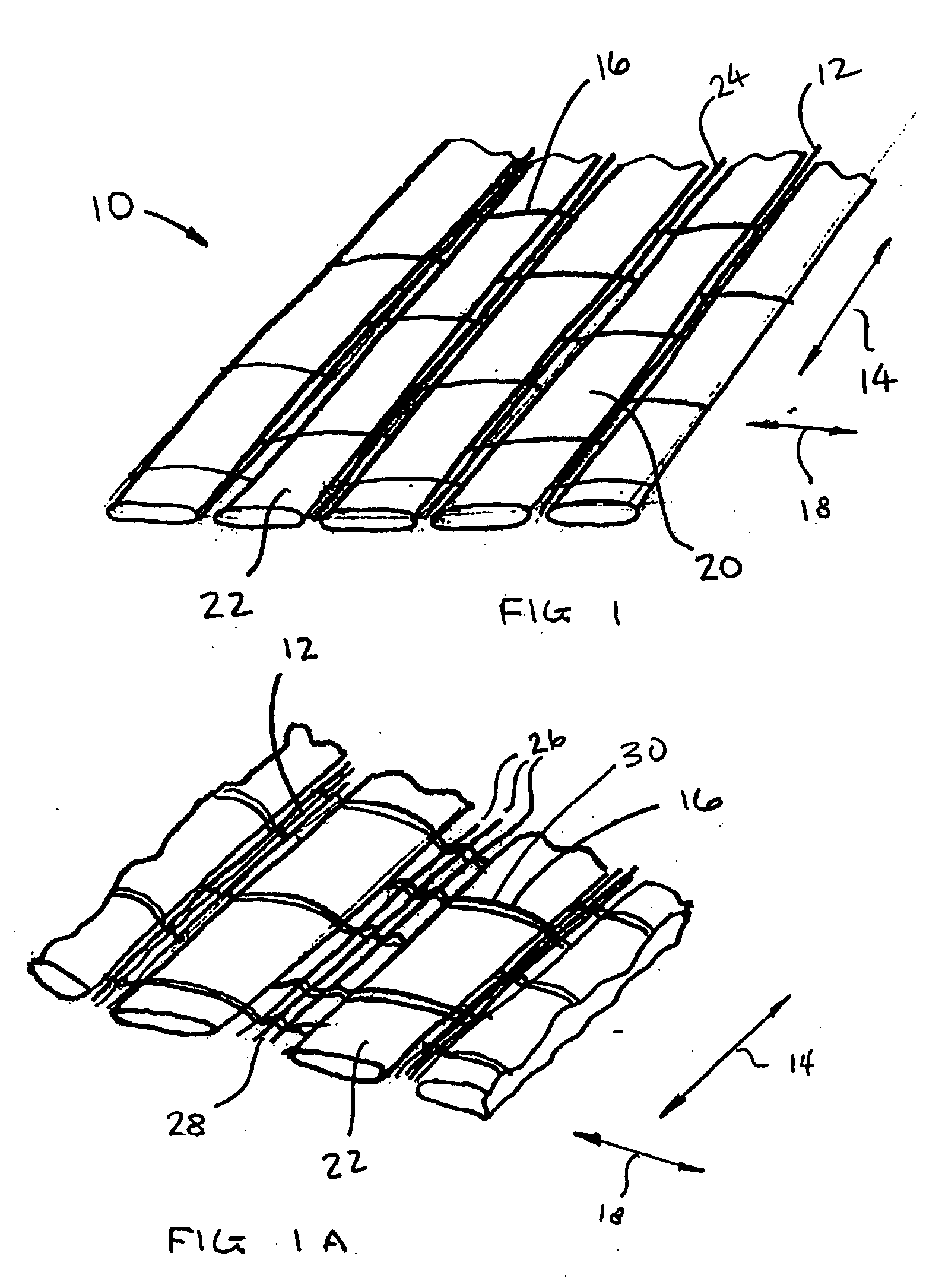
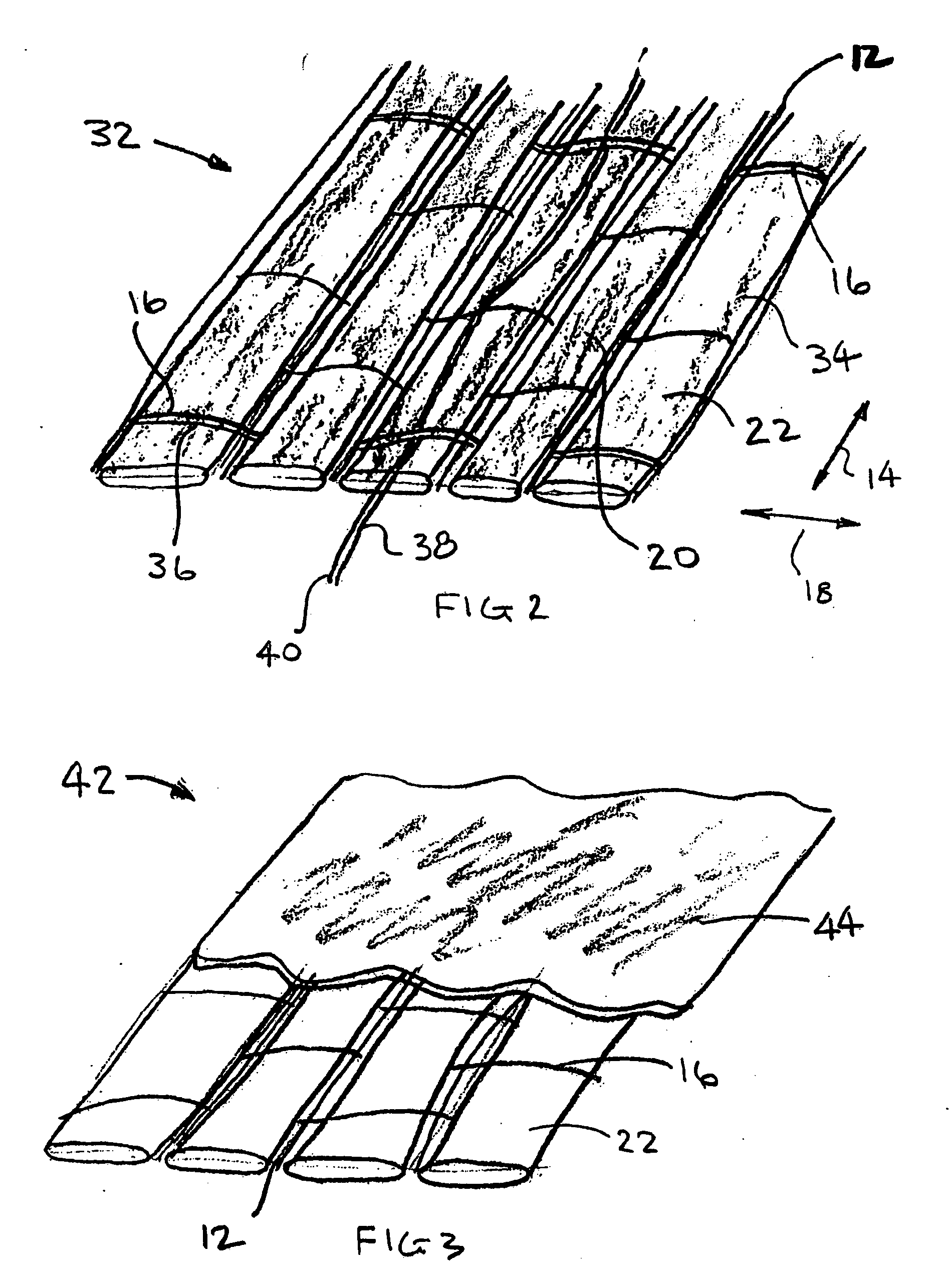
[0018]FIG. 1 shows a perspective view of a substrate according to the invention. Substrate 10 is formed from a plurality of first filamentary members 12 oriented in a first direction, indicated by arrow 14. For a woven substrate, the direction indicated by arrow 14 corresponds to the warp direction. Filamentary members 12 are interlaced with a plurality of second filamentary members 16. Second filamentary members 16 are oriented transversely to the first filamentary members as indicated by arrow 18. In a woven substrate, the direction indicated by arrow 18 corresponds to the weft or fill direction. First filamentary members 12 are positioned in spaced apart relation relative to one another, as are the second filamentary members 16, This results in relatively large interstices 20 being formed by the interlacing of the first and second filamentary members. Weaving is a preferred method for interlacing the filamentary members, although warp knitting is also feasible.

[0019] Substrate 1...


PUM

PropertyMeasurementUnit
circular shapeaaaaaaaaaa
electrically conductingaaaaaaaaaa
electrically conductiveaaaaaaaaaa

Abstract

The invention provides a substrate. The substrate includes a plurality of first filamentary members oriented in a first direction. The first filamentary members are arranged in spaced apart relation to one another. The substrate also includes a plurality of second filamentary members oriented in a second direction transverse to the first direction. The second filamentary members are spaced apart from one another. The second filamentary members are interlaced with the first filamentary members to define an open mesh. The substrate also includes a plurality of elongated strips of non-woven material oriented in the first direction. Each of the non-woven strips is positioned between at least two of the first filamentary members and interlaced with the second filamentary members.

Description

CROSS-REFERENCE TO RELATED APPLICATIONS [0001] This application claims the benefit of U.S. Provisional Patent Application Ser. No. 60 / 665,072 for a WOVEN OR KNITTED SUBSTRATE INCORPORATING NON-WOVEN ELEMENTS, filed on Mar. 24, 2005, which is hereby incorporated by reference in its entirety.BACKGROUND OF THE INVENTION [0002] 1. Field of the Invention [0003] The invention relates to textile substrates which are woven or knitted. [0004] 2. Description of Related Art [0005] Elongated items, such as wiring harnesses for example, may endure harsh environmental conditions in automotive, aerospace and marine applications. For example, wiring harnesses may be subjected to vibrations during vehicle operation which can cause abrasion of electrical insulation and result in short circuits. The harnesses may also be exposed to extreme high temperatures due to incident radiant heat, particularly in engine compartments. Furthermore, the harnesses may be subjected to radio frequency or electromagnet...

Claims


Application Information

Patent Timeline
Patent Type & Authority Applications(United States)
IPC IPC(8): D04H13/00
CPCD03D1/0047F41H1/02D03D3/02D03D9/00D03D11/00D03D15/00D03D15/0011D03D15/0066D03D15/0088D03D15/02D03D15/08D04B21/16D04H3/04D04H3/10D04H13/001D04H13/007D10B2101/06D10B2101/12D10B2101/20D10B2321/022D10B2331/02D10B2331/021D10B2331/04D10B2401/062D10B2401/16D10B2403/02411D10B2505/00D03D1/0058D10B2505/12D10B2403/0112D10B2401/041D03D15/258D03D15/267D03D15/46D03D15/593D03D15/56D03D1/0043D03D15/587D03D15/283D04H13/00
Inventor GLADFELTER, HARRY F.SELLIS, TIMOTHY D.LAURENT, BENOITBAER, ANGELA L.
Owner FEDERAL MOGUL WORLD WIDE
Why Eureka
Eureka Blog
Learn More