Method and apparatus for uniformity and brightness correction in an OLED display

a technology of brightness correction and uniformity, applied in the field of oled displays, can solve the problems of limiting the quality of the display, oled displays suffering from non-uniformity of light-emitting elements, and overall reduction in the dynamic range and brightness of the display, so as to reduce the complexity of calculations, minimize the amount of data, and improve the uniformity of the display

Active Publication Date: 2006-10-05
GLOBAL OLED TECH
View PDF13 Cites 51 Cited by
  • Summary
  • Abstract
  • Description
  • Claims
  • Application Information

AI Technical Summary

Problems solved by technology

However, such displays suffer from a variety of defects that limit the quality of the displays.
In particular, OLED displays suffer from non-uniformities in the light-emitting elements.
These non-uniformities can be attributed to both the light emitting materials in the display and, for active-matrix displays, to variability in the thin-film transistors used to drive the light emitting elements.
However, this approach will lead to an overall reduction in the dynamic range and brightness of the display and a reduction and variation in the bit depth at which the pixels can be operated.
However, the described approaches require either a lookup table providing a complete characterization for each pixel, or extensive computational circuitry within a device controller.
This is likely to be expensive and impractical in most applications.

Method used


Image

  • Method and apparatus for uniformity and brightness correction in an OLED display
  • Method and apparatus for uniformity and brightness correction in an OLED display
  • Method and apparatus for uniformity and brightness correction in an OLED display

Examples


Embodiment Construction

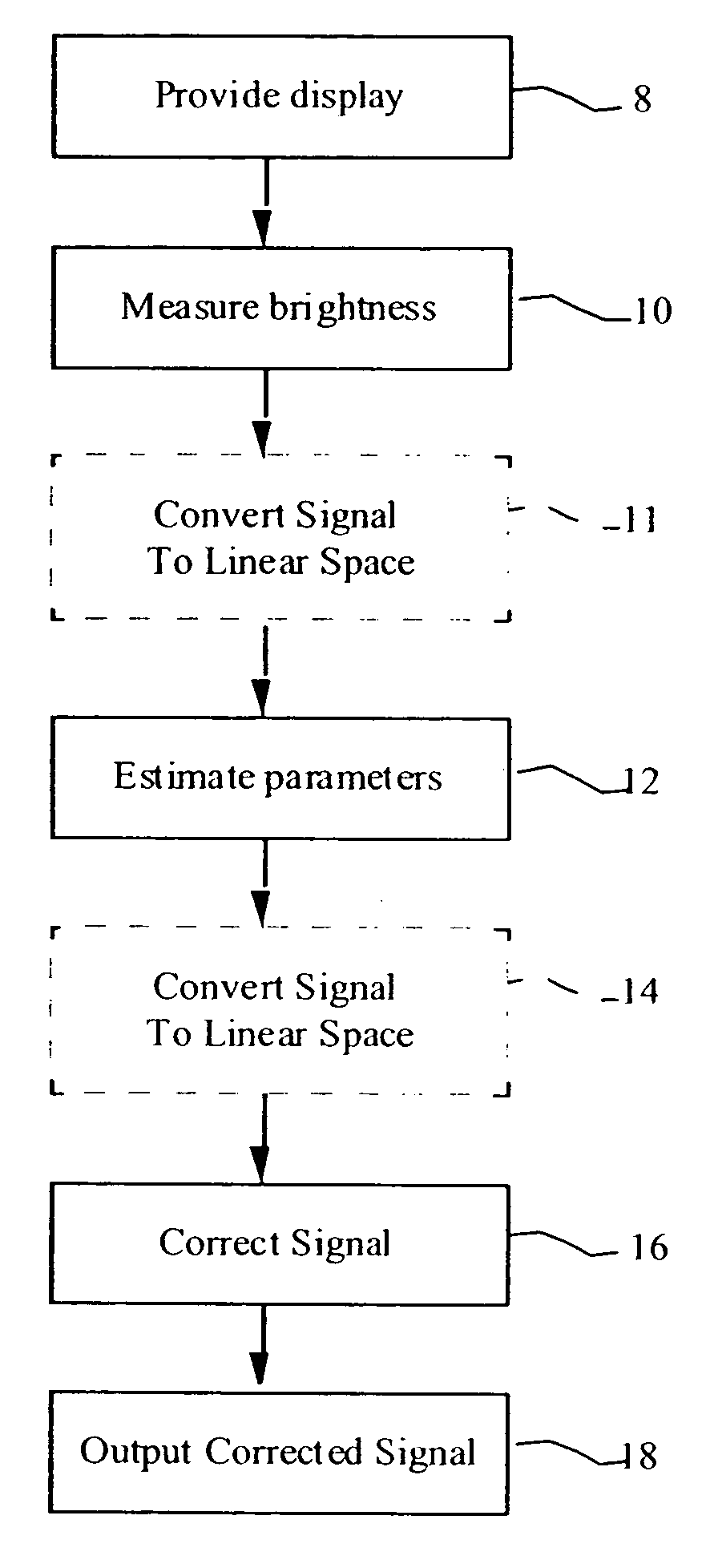
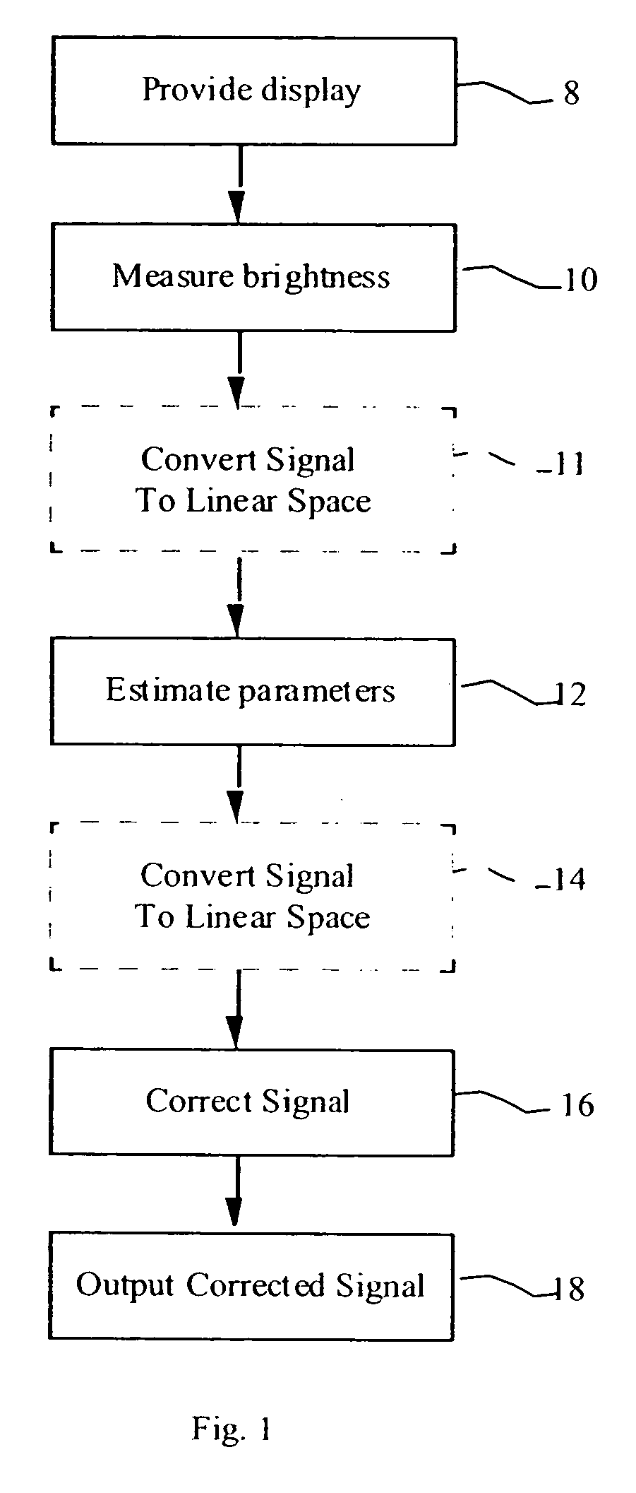
[0019] Referring to FIG. 1, the present invention is directed to a method and apparatus for the correction of brightness and uniformity variations in OLED displays, comprising providing 8 an OLED display having one or more light-emitting elements responsive to a multi-valued input signal for causing the light-emitting elements to emit light at a plurality of brightness levels; measuring 10 the brightness of each light-emitting element at two or more, but fewer than all possible, different input signal values; employing the measured brightness values to estimate 12 a maximum input signal value at which the light-emitting element will not emit more than a predefined minimum brightness (the offset) and the rate at which the brightness of the light-emitting element increases above the predefined minimum brightness in response to increases in the value of the input signal (the gain); and using the estimated maximum input signal value at which the light-emitting element will not emit ligh...


PUM


Abstract

A method for the correction of average brightness or brightness uniformity variations in OLED displays comprising: a) providing an OLED display having one or more light-emitting elements responsive to a multi-valued input signal for causing the light-emitting elements to emit light at a plurality of brightness levels; b) measuring the brightness of each light-emitting element at two or more, but fewer than all possible, different input signal values; c) employing the measured brightness values to estimate a maximum input signal value at which the light-emitting element will not emit more than a predefined minimum brightness and the rate at which the brightness of the light-emitting element increases above the predefined minimum brightness in response to increases in the value of the input signal; and d) using the estimated maximum input signal value at which the light-emitting element will not emit light more than the predefined minimum brightness and the rate at which the brightness of the light-emitting element increases above the predefined minimum brightness in response to increases in the value of the input signal to modify the input signal to a corrected input signal to correct the light output of the light-emitting elements.

Description

FIELD OF THE INVENTION [0001] The present invention relates to OLED displays having a plurality of light-emitting elements and, more particularly, to correcting brightness of the light-emitting elements in the display. BACKGROUND OF THE INVENTION [0002] Organic Light Emitting Diodes (OLEDs) have been known for some years and have been recently used in commercial display devices. Such devices employ both active-matrix and passive-matrix control schemes and can employ a plurality of light-emitting elements. The light-emitting elements are typically arranged in two-dimensional arrays with a row and a column address for each light-emitting element and having a data value associated with each light-emitting element to emit light at a brightness corresponding to the associated data value. However, such displays suffer from a variety of defects that limit the quality of the displays. In particular, OLED displays suffer from non-uniformities in the light-emitting elements. These non-uniform...

Claims


Application Information

Patent Timeline
Patent Type & Authority Applications(United States)
IPC IPC(8): G01J1/00
CPCG09G3/3208G09G3/3225G09G2320/0233G09G2320/045G09G2320/029G09G2320/0295G09G2320/043G09G2320/0285
Inventor COK, RONALD S.FORD, JAMES H.
Owner GLOBAL OLED TECH
Why Eureka
Try Eureka