Balloon catheter with expandable wire lumen

a balloon catheter and expandable wire technology, applied in balloon catheters, coatings, surgery, etc., can solve the problem that current catheter systems do not provide both a mechanism and a mechanism adequately

Inactive Publication Date: 2006-10-05
BOSTON SCI SCIMED INC
View PDF43 Cites 36 Cited by
  • Summary
  • Abstract
  • Description
  • Claims
  • Application Information

AI Technical Summary

Benefits of technology

[0014] In at least one embodiment, the invention is directed to a catheter comprising an outer shaft and an inner shaft. The inner shaft may have an inner shaft wall defining a guidewire lumen for passage of a guidewire. In at least one embodiment, the catheter may further comprise an expandable balloon. In at least one embodiment, the inner and outer shafts may define a balloon inflation lumen for transport of an inflation fluid there through. In at least one embodiment, the expandable balloon may have a proximal waist portion and a distal waist portion with a body portion there between. In at least one embodiment, the balloon may be engaged to a distal region of the at least one outer shaft and may define an exterior and an interior. In at least one embodiment, the interior may be in fluid communication with the balloon inflation lumen. In at least one embodiment, a distal portion of the inner shaft may be expandable. In at least one embodiment, the inner shaft may be constructed and arranged to release infusate onto the surrounding tissue without removal of an extant guidewire. In at least one embodiment the guidewire may help diffuse the infusate as it passes through the guidewire lumen.

Problems solved by technology

However current catheter systems do not adequately provide both a mechanism for establishing re-profusion and providing a cooling effect within the desired window.

Method used


Image

  • Balloon catheter with expandable wire lumen
  • Balloon catheter with expandable wire lumen
  • Balloon catheter with expandable wire lumen

Examples


Embodiment Construction

[0061] While this invention may be embodied in many different forms, there are described in detail herein specific preferred embodiments of the invention. This description is an exemplification of the principles of the invention and is not intended to limit the invention to the particular embodiments illustrated.

[0062] For the purposes of this disclosure, like reference numerals in the figures shall refer to like features unless otherwise indicated.

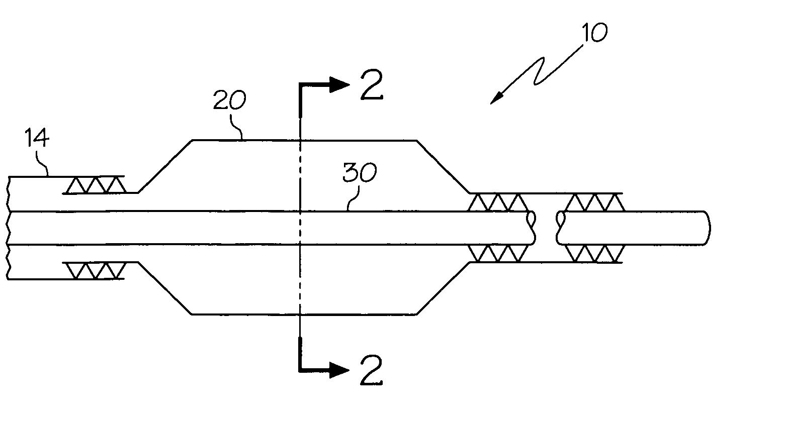
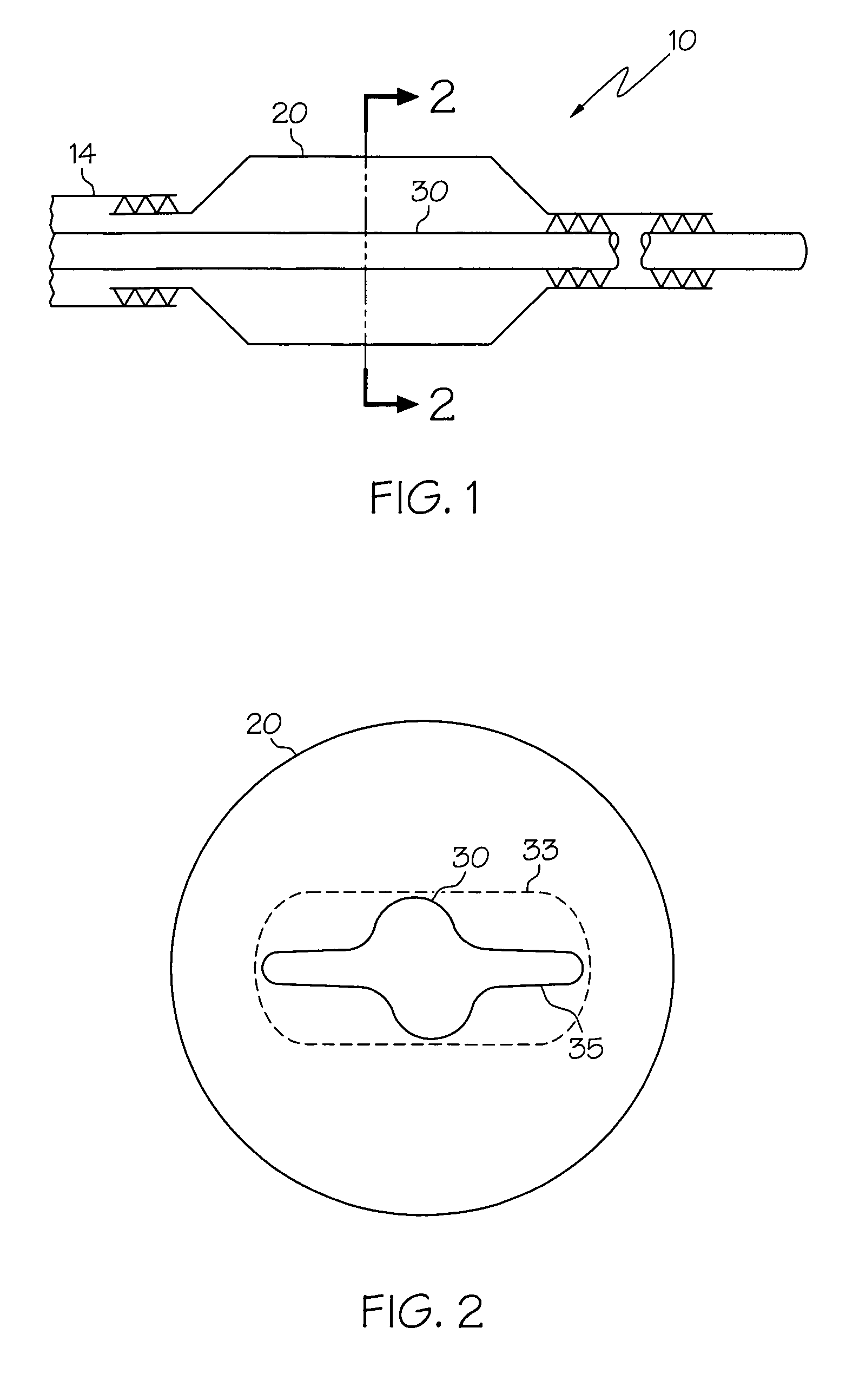
[0063] In at least one embodiment, an example of which is shown in FIG. 1, the catheter 10 may have an outer shaft 14, a balloon 20, and an inner shaft 30. In at least one embodiment, the inner shaft may be expandable as illustrated in FIG. 2. FIG. 2 illustrates the cross-section of FIG. 1 along lines A-A. The inner shaft may be in a relatively expanded state 33 or a relatively unexpanded state 35. In the unexpanded state portions of the shaft 30 may fold over on other portions of the shaft. The inner shaft may be self expanding or expa...


PUM

PropertyMeasurementUnit
diameteraaaaaaaaaa
diameteraaaaaaaaaa
diameteraaaaaaaaaa

Abstract

A catheter comprises an outer shaft and an inner shaft defining a balloon inflation lumen for transport of an inflation fluid therethrough. The expandable balloon has a proximal waist portion and a distal waist portion with a body portion there between. The balloon is engaged to a distal region of the outer shaft and defines an exterior and an interior where the interior is in fluid communication with the balloon inflation lumen. The inner shaft has an inner shaft wall defining a guidewire lumen for passage of a guidewire. A distal portion of the inner shaft is expandable from an unexpanded state to an expanded state such that in the expanded state the guidewire lumen has a greater cross-sectional area than in the unexpanded state.

Description

CROSS-REFERENCE TO RELATED APPLICATIONS [0001] Not Applicable STATEMENT REGARDING FEDERALLY SPONSORED RESEARCH [0002] Not Applicable BACKGROUND OF THE INVENTION [0003] 1. Field of the Invention [0004] This invention embodies such areas as those related to catheters and catheter assemblies for use in medical procedures. In more specific embodiments, this invention relates to catheter systems, including those used in percutaneous transluminal angioplasty (PTA), cryoplasty and / or cooling procedures, etc. [0005] 2. Description of the Related Art [0006] Percutaneous transluminal angioplasty (PTA) is a procedure which is well established for the treatment of blockages, lesions, stenosis, thrombus, etc. present in body lumens such as the peripheral or coronary arteries and / or other vessels. [0007] A widely used form of percutaneous transluminal angioplasty makes use of a dilatation balloon catheter which is introduced into and advanced through a lumen or body vessel until the distal end th...

Claims


Application Information

Patent Timeline
Patent Type & Authority Applications(United States)
IPC IPC(8): A61M29/00
CPCA61M25/0045A61M25/1011A61M25/104A61M2025/1095A61M2025/1013A61M2025/105A61M2025/0004
Inventor WILLARD, MARTIN R.
Owner BOSTON SCI SCIMED INC
Why Eureka
Try Eureka