Method and apparatus for reducing mitral regurgitation

a technology of mitral valve and mitral valve, applied in the field of surgical methods and equipment, can solve the problems of symptomatic mitral regurgitation being denied early intervention, high morbidity and mortality, and many sickest patients being denied the potential benefits of surgical correction, so as to reduce the incidence of symptomatic mitral regurgitation

a technology of mitral valve and mitral valve, applied in the field of surgical methods and equipment, can solve the problems of symptomatic mitral regurgitation being denied early intervention, high morbidity and mortality, and many sickest patients being denied the potential benefits of surgical correction, so as to reduce the incidence of symptomatic mitral regurgitation

US20060229717A1Inactive Publication Date: 2006-10-12COHN WILLIAM E +4

Image

  • Method and apparatus for reducing mitral regurgitation
  • Method and apparatus for reducing mitral regurgitation
  • Method and apparatus for reducing mitral regurgitation

Examples


Embodiment Construction

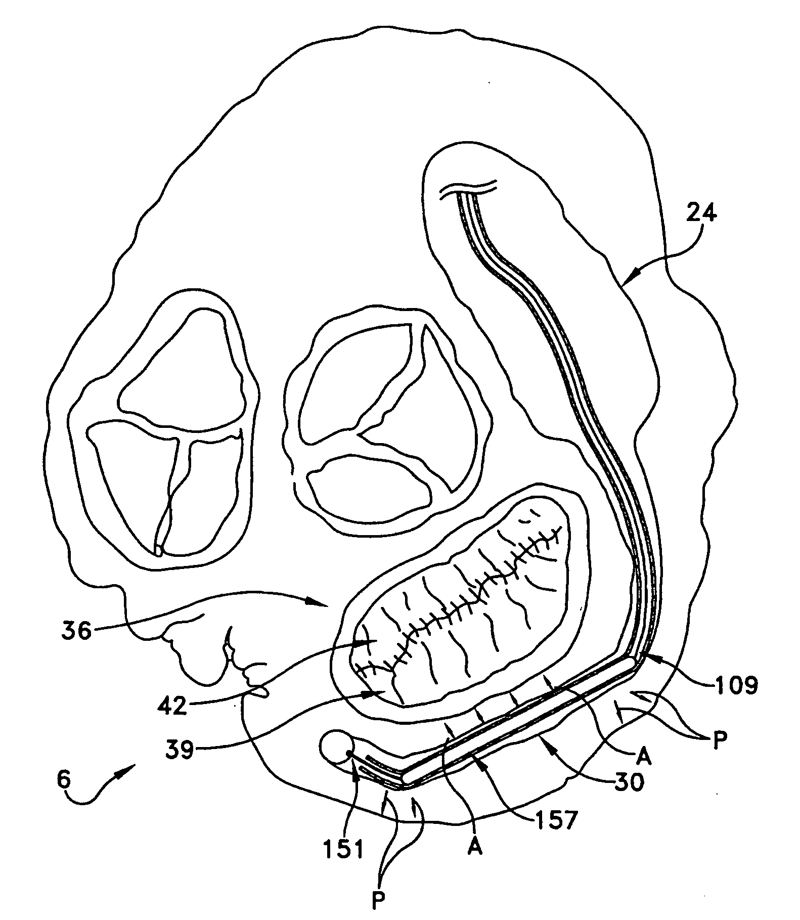
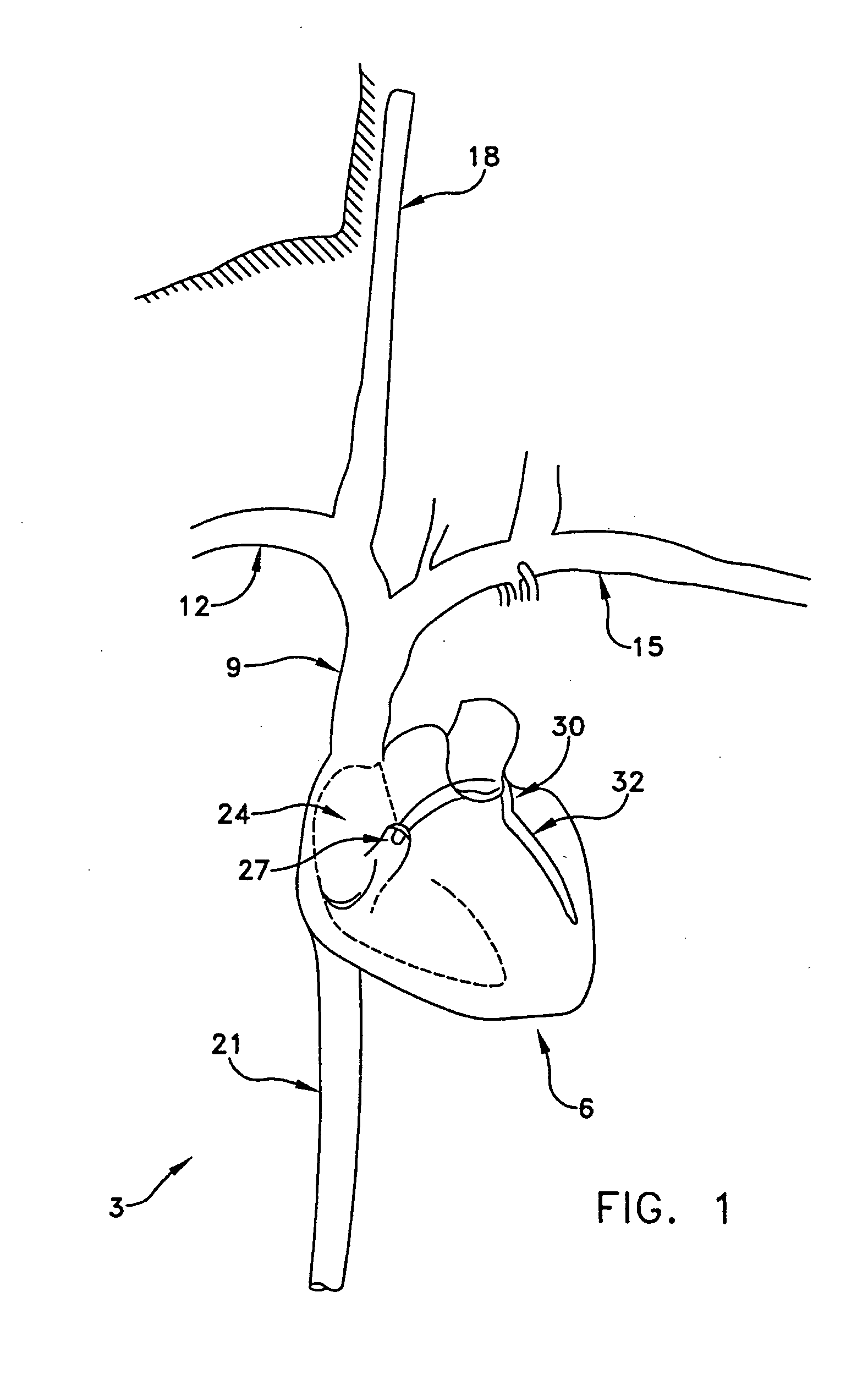
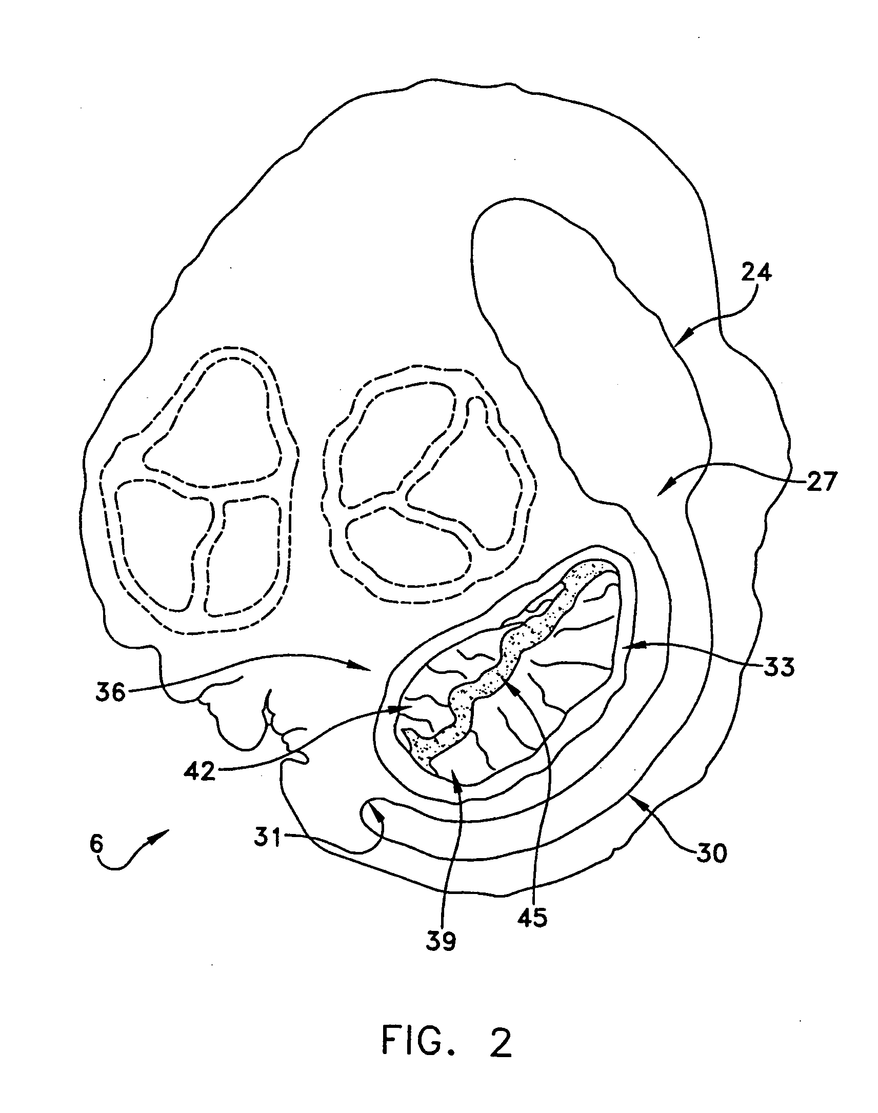
[0070] The coronary sinus is the largest vein in the r human heart. During a large portion of its course in the atrioventricular groove, the coronary sinus typically extends adjacent to the left atrium of the heart for a distance of approximately 5 to 10 centimeters. Significantly, for a portion of its length, e.g., typically approximately 7-9 cm, the coronary sinus extends substantially adjacent to the posterior perimeter of the mitral annulus. The present invention takes advantage of this consistent anatomic relationship. More particularly, by deploying novel apparatus in the coronary sinus, adjacent to the posterior leaflet of the mitral valve, the natural curvature of the coronary sinus may be modified in the vicinity of the posterior leaflet of the mitral valve, whereby to move the posterior annulus anteriorly so as to improve leaflet coaptation and, as a result, reduce mitral regurgitation.

[0071] In one preferred embodiment of the invention, the novel apparatus comprises a st...


PUM


Abstract

A method for reducing mitral regurgitation includes deploying deforming matter into a selected one of (i) a mitral valve annulus adjacent a posterior leaflet, and (ii) tissue adjacent the mitral valve annulus and proximate the posterior leaflet, to cause conformational change in the mitral valve annulus to increase mitral valve leaflet coaptation.

Description

REFERENCE TO PENDING PRIOR PATENT APPLICATIONS [0001] This patent application: [0002] (1) is a continuation-in-part of pending prior U.S. patent application Ser. No. 10 / 068,264, filed Feb. 5, 2002 by Daniel C. Taylor et al. for METHOD AND APPARATUS FOR IMPROVING MITRAL VALVE FUNCTION (Attorney's Docket No. VIA-29); [0003] (2) is a continuation-in-part of pending prior U.S. patent application Ser. No. 10 / 112,354, filed Mar. 29, 2002 by John Liddicoat et al. for METHOD AND APPARATUS FOR IMPROVING MITRAL VALVE FUNCTION (Attorney's Docket No. VIA-19202122); [0004] (3) is a continuation-in-part of pending prior U.S. patent application Ser. No. 10 / 218,649, filed Aug. 14, 2002 by Daniel C. Taylor et al. for METHOD AND APPARATUS FOR IMPROVING MITRAL VALVE FUNCTION (Attorney's Docket No. VIA-23); [0005] (4) claims benefit of pending prior U.S. Provisional Patent Application Ser. No. 60 / 339,481, filed Oct. 26, 2001 by William E. Cohn et al. for TRANSVASCULAR APPROACH TO MITRAL VALVE PROCEDURE...

Claims


Application Information

Patent Timeline
12 Oct 2006
Publication
US20060229717A1
IPC
A61F2/24; A61B17/34; A61F; A61F2/00; A61F2/02; A61F6/00
CPC
A61B17/3468; A61B17/3478; A61B2017/00247; Y10S623/904; A61F2/2451; A61F2250/0007; A61F2250/0063; A61B2018/00392
Inventors
COHN, WILLIAM E.; LIDDICOAT, JOHN R.