Apparatus and method for treating a regurgitant heart valve

Active Publication Date: 2009-05-21
THE CLEVELAND CLINIC FOUND
View PDF34 Cites 46 Cited by
  • Summary
  • Abstract
  • Description
  • Claims
  • Application Information

AI Technical Summary

Benefits of technology

[0011]According to another aspect of the present invention, a method is provided for treating regurgitation of blood flow through a diseased heart valve. The diseased heart valve includes an annulus, an anterior valve leaflet, and a posterior valve leaflet. Each of the anterior and posterior valve leaflets has a free edge. One step of the method comprises providing an apparatus including an annular support member and at least one leaflet support member securely connected to the annular support member. The annular support member comprises an anterior end portion, a posterior end portion, and oppositely disposed first and second intermediate po

Problems solved by technology

When the high pressure produced by contraction of the left ventricle pushes the valve leaflets too much, the leaflets become everted and prolapse results.
Mitral valve malfunction can result from the chords becoming stretched and, in some cases, tearing.
When a chord tears, for example, the result is a flailed or p

Method used


Image

  • Apparatus and method for treating a regurgitant heart valve
  • Apparatus and method for treating a regurgitant heart valve
  • Apparatus and method for treating a regurgitant heart valve

Examples


Embodiment Construction

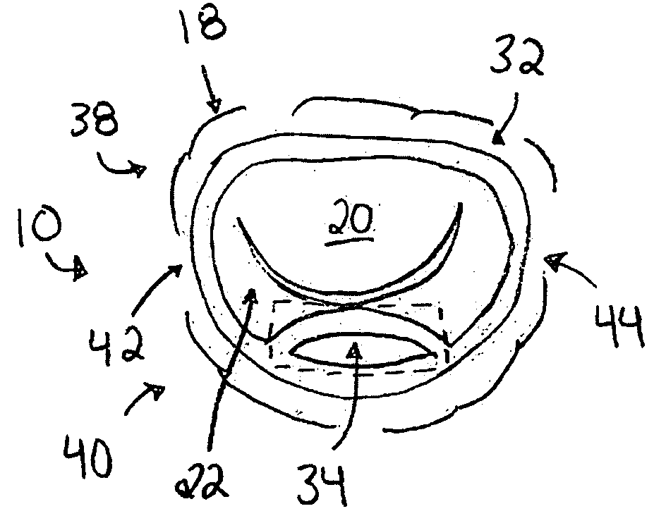
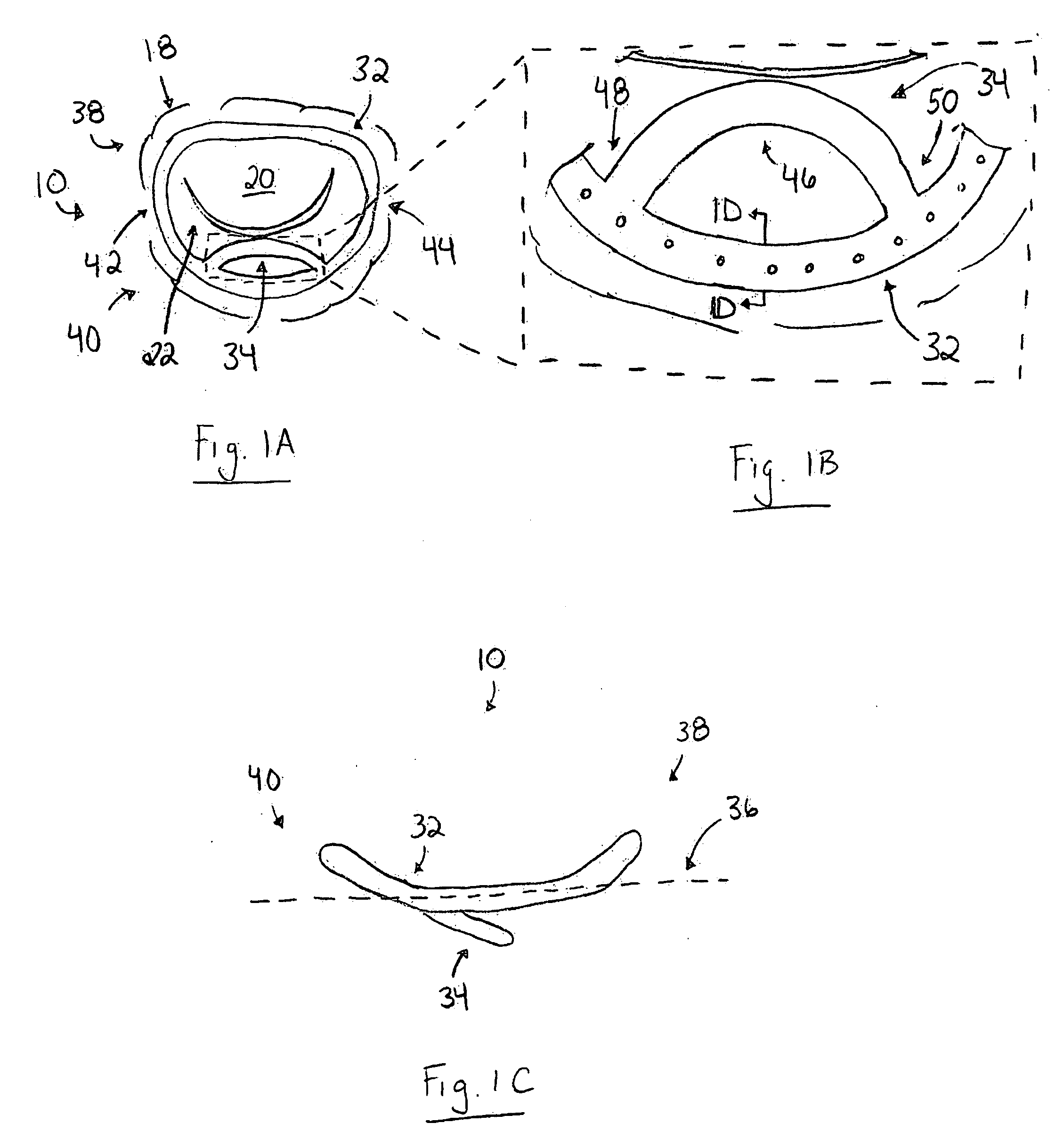
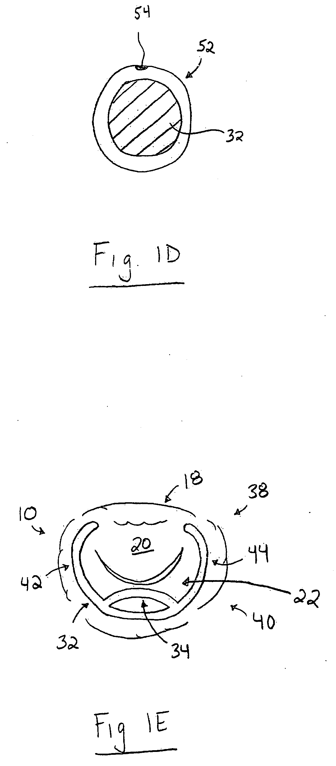
[0065]The present invention relates generally to apparatus and methods for treating dysfunctional heart valves, and more particularly to apparatus and related methods that passively assist in preventing or mitigating heart valve prolapse. As representative of the present invention, FIGS. 1A-E illustrate an apparatus 10 for treating regurgitation of blood flow through a diseased heart valve, such as a mitral valve 12 (FIG. 2). It should be appreciated that although the present invention is described herein as being used to treat mitral regurgitation through a diseased mitral valve 12, the apparatus 10 can also be used to treat other cardiac valves, such as the tricuspid valve (not shown).

[0066]As shown in FIG. 2, the mitral valve 12 is located between the left atrium 14 and the left ventricle 16, and functions to prevent the backflow of blood from the left ventricle into the left atrium during contraction. The mitral valve 12 has a D-shaped annulus 18 that defines the opening between...


PUM


Abstract

An apparatus is provided for treating regurgitation of blood flow through a diseased heart valve. The apparatus includes an annular support member and at least one posterior leaflet support member. The annular support member has an anterior end portion, a posterior end portion, and oppositely disposed first and second intermediate portions extending between the end portions. The at least one posterior leaflet support member is securely connected to the annular support member and is dimensioned to extend across a portion of a free edge of a posterior valve leaflet. The posterior leaflet support member comprises an arcuate center portion integrally formed with and extending between first and second end portions. The arcuate center portion has a concave shape relative to the anterior end portion. At least one of the first and second end portions is securely attached to the posterior end portion.

Description

RELATED APPLICATION[0001]This application claims priority from U.S. Provisional Application No. 60 / 988,825, filed Nov. 19, 2007, the subject matter of which is incorporated herein by reference.TECHNICAL FIELD[0002]The present invention relates generally to apparatus and methods for treating dysfunctional heart valves, and more particularly to apparatus and related methods that passively assist in preventing or mitigating heart valve prolapse.BACKGROUND OF THE INVENTION[0003]The opening and closing of heart valves occur primarily as a result of pressure differences. For example, the opening and closing of the mitral valve occurs as a result of the pressure differences between the left atrium and the left ventricle. During ventricular diastole, the venous return of blood from the pulmonary veins into the left atrium causes the pressure in the atrium to exceed that in the left ventricle. As a result, the mitral valve opens and allows blood to enter the left ventricle. As the left ventr...

Claims


Application Information

Patent Timeline
IPC IPC(8): A61F2/24A61B19/00
CPCA61F2/2445A61F2/2448A61F2/2496A61F2/246A61F2/2466A61F2/2454
Inventor NAVIA, JOSE LUIS
Owner THE CLEVELAND CLINIC FOUND
Why Eureka
Try Eureka