X-ray CT apparatus and myocardial perfusion image generating system

a computed tomography and generating system technology, applied in the field of x-ray ct (computed tomography) devices and myocardial perfusion image generating systems, can solve the problems of inability to use long-period dynamic imaging using an x-ray ct apparatus, inability to increase the dose of subject rays, and inability to achieve long-period dynamic imaging. , to achieve the effect of reducing the amount of contrast medium injection

Active Publication Date: 2006-10-26
THE JOHN HOPKINS UNIV SCHOOL OF MEDICINE +1
View PDF13 Cites 53 Cited by
  • Summary
  • Abstract
  • Description
  • Claims
  • Application Information

AI Technical Summary

Benefits of technology

[0018] Such an X-ray CT apparatus and a myocardial perfusion image generating system according to the present invention generate a myocardial perfusion image in a shorter time while reducing the amount of injection of a contrast medium to a subject, as well as X-ray dosage.

Problems solved by technology

However, normally, such perfusion imaging is not an isolated examination, but performed as part of a contrast examination.
Accordingly, it takes a long time for scanning of a myocardial perfusion image, and a examination method resulting in increase of X-ray dosages for the subject ray is hardly acceptable, and accordingly, long-period dynamic imaging using an X-ray CT apparatus has never come into practical use so far.
However, the amount of injection of the contrast medium as to a subject has an upper limit, and consequently, the amount of time for imaging and the number of times thereof are also restricted.
Accordingly, this presents a problem in that it is difficult to secure long imaging time for myocardial perfusion images.

Method used


Image

  • X-ray CT apparatus and myocardial perfusion image generating system
  • X-ray CT apparatus and myocardial perfusion image generating system
  • X-ray CT apparatus and myocardial perfusion image generating system

Examples


Embodiment Construction

[0029] An X-ray CT apparatus and a myocardial perfusion image generating system according to the present invention will now be described in further detail below with reference to embodiments in conjunction with the accompanying drawings.

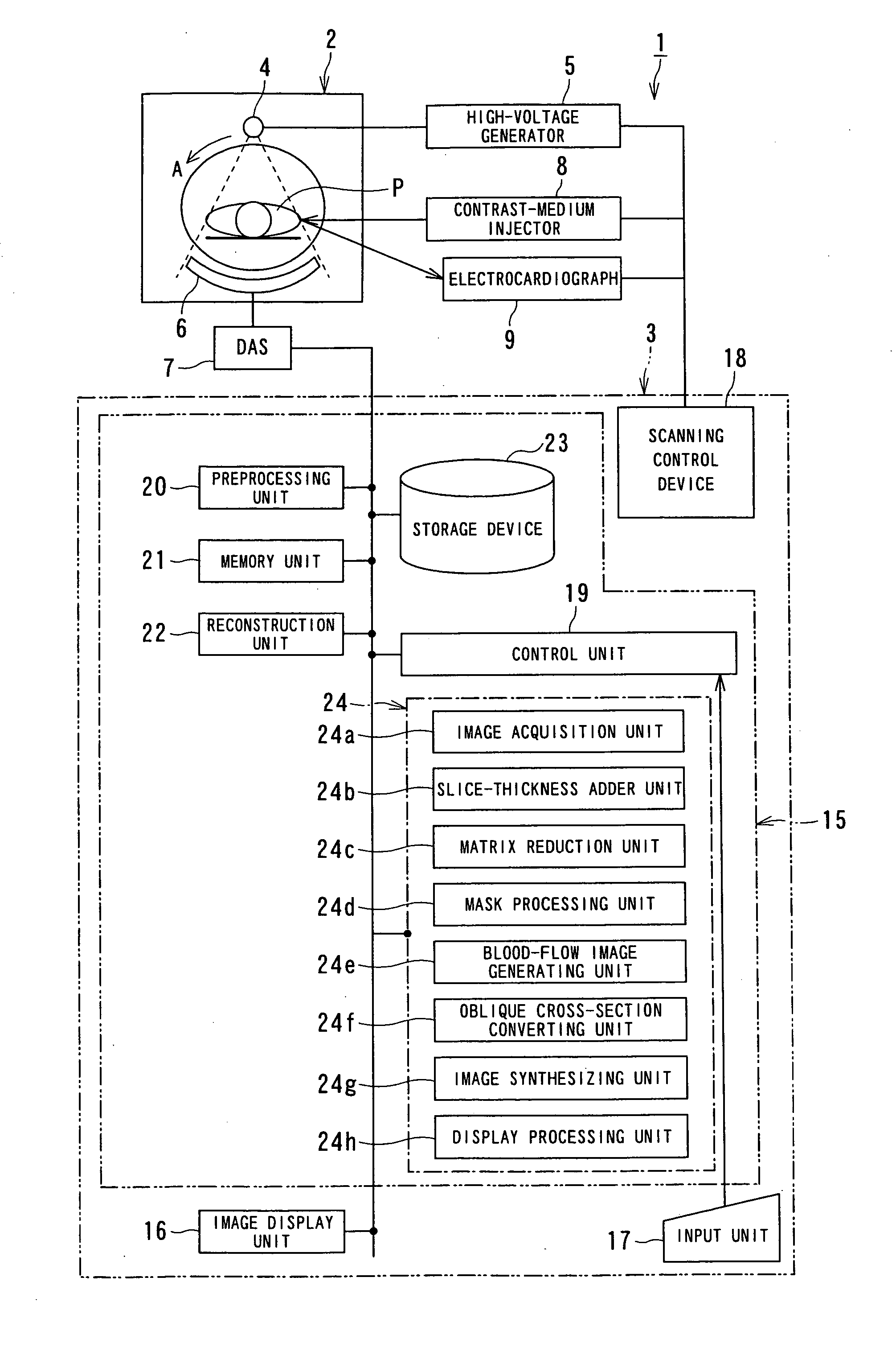
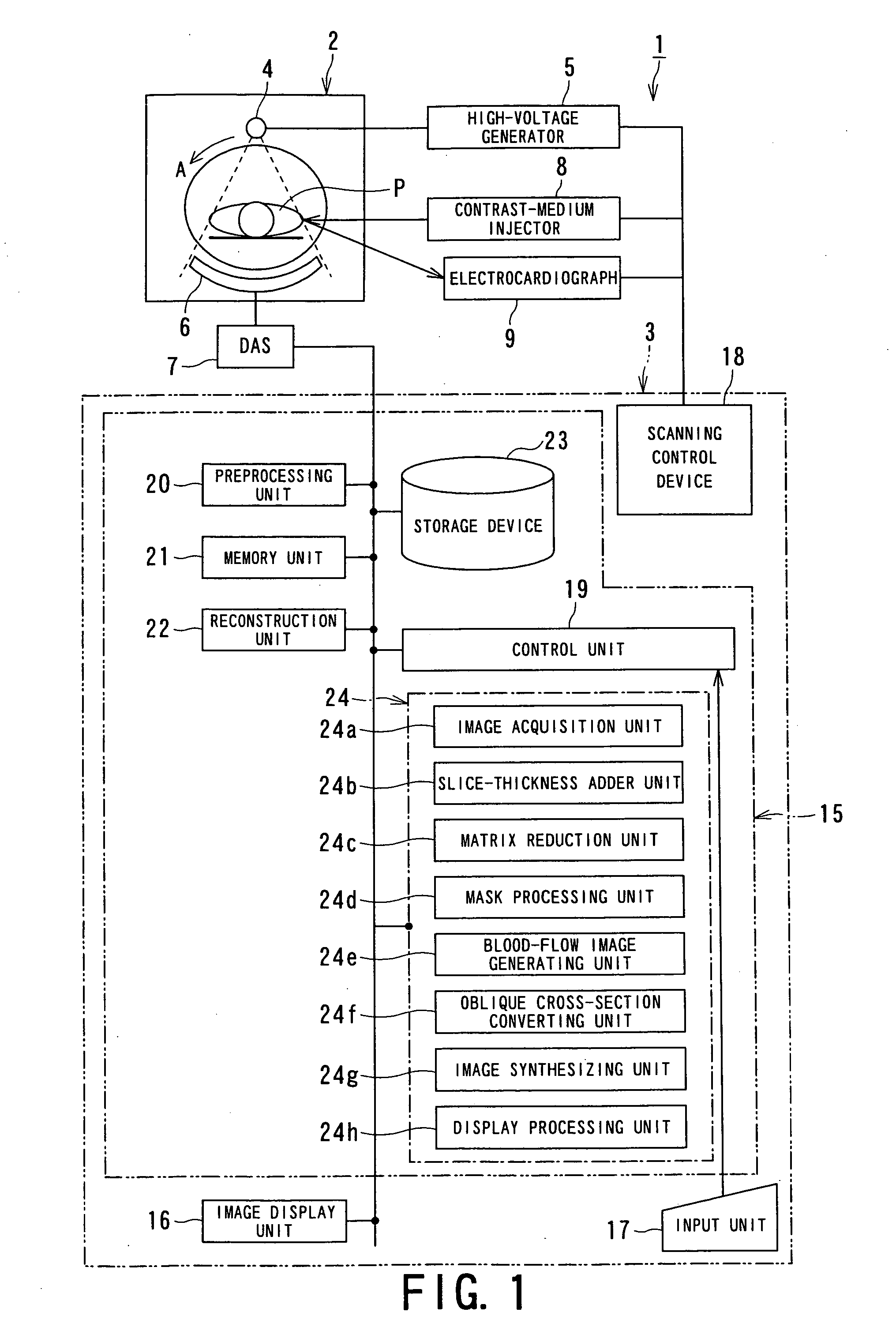
[0030]FIG. 1 is a configuration diagram illustrating an X-ray CT apparatus according to an embodiment of the present invention. An X-ray CT apparatus 1 comprises a gantry unit 2 and a computer device 3. The gantry unit 2 includes an X-ray tube 4, high-voltage generator 5, X-ray detector 6, DAS (Data Acquisition System) 7, contrast-medium injector 8, and electrocardiograph 9. The X-ray tube 4 and X-ray detector 6 are mounted at positions facing each other sandwiching a subject P in an unshown rotating ring consecutively rotating at a high speed.

[0031] The contrast-medium injector 8, which is controlled by a control signal from the computer device 3, has a function for continuously injecting a contrast medium into the subject P in accordance accordin...


PUM


Abstract

An X-ray CT apparatus 1 comprises a blood-flow information acquisition unit, a correction value calculating unit and a blood-flow image generating unit 24 e. The blood-flow information acquisition unit obtains information of a relative blood flow rate in the myocardium of the subject P based on the CT image. The correction value calculating unit obtains a correction value based on the CT image in a concentration transition period defined to be a period from immediately after starting of a continuously injection of a contrast medium into the subject P until the contrast medium injected reaches to the myocardium, increases, and will be in a state where it can be considered that the contrast medium is saturated in a constant value. The blood-flow image generating unit 24 e generating a blood flow value image in the myocardium by correcting the information of the relative blood flow rate with the correction value.

Description

BACKGROUND OF THE INVENTION [0001] 1. Field of the Invention [0002] The present invention relates to an X-ray CT (computed tomography) device and a myocardial perfusion image generating system for taking contrast CT images such as coronary arterial contrast CT images, myocardial contrast CT images, and so forth, by continuously injecting a contrast medium, and generating a myocardial perfusion image using the obtained contrast CT images. [0003] 2. Description of the Related Art [0004] With a myocardial contrast examination using an X-ray CT apparatus, a contrast medium is injected into a subject that is a patient, and contrast CT images are collected. Subsequently, moving images of coronary arteries, endocardial lumen wall, and so forth, are generated from the collected contrast CT images, and are employed for diagnosis. [0005] Also, a blood flow dynamic state (perfusion) examination of the myocardium and a perfusion examination regarding organs such as within a brain tissue have be...

Claims


Application Information

Patent Timeline
Patent Type & Authority Applications(United States)
IPC IPC(8): A61B5/05
CPCA61B6/481A61B6/503A61B6/507A61B6/541A61B6/504
Inventor ICHIHARA, TAKASHIRIFU, TOSHIHIROLIMA, JOAO A.C.
Owner THE JOHN HOPKINS UNIV SCHOOL OF MEDICINE
Why Eureka
Try Eureka