Bag-in-a-box
a bag and box body technology, applied in the field of bags, can solve the problems of inconvenience of manually mounting the spigot to the exterior sidewall of the carton
- Summary
- Abstract
- Description
- Claims
- Application Information
AI Technical Summary
Benefits of technology
Problems solved by technology
Method used
Image

Examples
first embodiment
[0057] In accordance with the first embodiment, the box 24 is a rectangular parallelepiped when closed. As best understood with reference to FIGS. 8-10, the box 24 has an access opening 29 at its front end, for providing access to the interior of the box 24. The access opening 29 can be opened and closed by the box's front cover panel. The front cover panel is typically in the form of four front flaps 30 respectively foldably connected along fold lines to the front edges of the top, bottom, right side and left side panels 32, 34, 36, 38 of the box 24. The front cover panel can be used for opening and closing the box's access opening 29.
[0058] Similarly, the box has a rear end (not shown) that is primarily kept closed by a rear cover panel (not shown). The rear cover panel is typically in the form of four rear flaps (not shown, but similar to the front flaps 30) respectively foldably connected along fold lines to the rear edges of the top, bottom, right side and left side panels 32, ...
second embodiment
[0093] With regard to the box's access opening 229 being closed and in accordance with the second embodiment, the placement of the gripping opening 242 is coordinated with the oblique arrangement of the holding flap 240 so that the spigot 244 is advantageously arranged in an interior corner 245 of the box 224, which is a beneficial compact arrangement. This compact arrangement is illustrated in FIG. 18, which schematically illustrates that the box's access opening 229 (FIG. 17) is closed by a closure panel 350 (e.g., formed by respectively overlapping and adhering together the end panels 230 of FIG. 17), and further illustrates in broken lines how the spigot 44 can be advantageously positioned in the interior corner 245. FIG. 18 illustrates that the spigot 44 is entirely enclosed in the interior of the box 224. In FIG. 18, the liner 240 is shown fully inserted into the box 224, but the neck 228 and bag 210 are omitted.
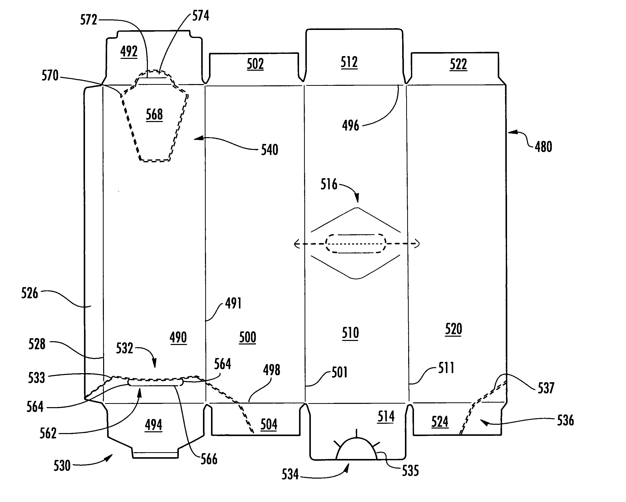
[0094] The liner 220 can be erected from the blank 222 illustrate...
third embodiment
[0125] First and second retention tabs 446, 448 may be disposed at upper opposed ends of the holding flap 432. The retention tabs 446, 448 are sized and shaped to be respectively received and retained in first and second retention apertures 450, 452 respectively in the first and second side panels 424, 426. The interaction respectively between the retention tabs 446, 448 and the retention apertures 450, 452 is for respectively connecting the opposite edges of the holding flap 432 to the side panels 424, 426 and thereby at least partially supporting the holding flap 432 in an upright configuration while the liner 470 is erected. As a result of the respective interaction between the retention tabs 446, 448 and retention apertures 450, 452, when the liner 470 is fully erected and within the box 550 in accordance with the third embodiment, not only are the side edges of the holding flap 432 respectively in opposing face-to-face contact with the inwardly facing faces of the liner's side ...
PUM
 Abstract
Description
Claims
Application Information
 - R&D
- Intellectual Property
- Life Sciences
- Materials
- Tech Scout
- Unparalleled Data Quality
- Higher Quality Content
- 60% Fewer Hallucinations
Browse by: Latest US Patents, China's latest patents, Technical Efficacy Thesaurus, Application Domain, Technology Topic, Popular Technical Reports.
© 2025 PatSnap. All rights reserved.Legal|Privacy policy|Modern Slavery Act Transparency Statement|Sitemap|About US| Contact US: help@patsnap.com