Carton with an interlocking divider pad

a technology of divider pads and cartons, applied in the field of cartons, can solve the problems of difficult removal of cans immediately adjacent to this end of the carton

Active Publication Date: 2005-06-02
GRAPHIC PACKAGING INT
View PDF20 Cites 87 Cited by
  • Summary
  • Abstract
  • Description
  • Claims
  • Application Information

AI Technical Summary

Benefits of technology

[0005] Briefly described, the present invention relates to a fully enclosed carton that is capable of carrying two layers of cans or other articles which has an interlocking separator, or divider, pad separating the two layers of cans or other articles. The carton has a bottom panel, top panel and foldably attached side panels. Preferably each end of the carton is closed by a pair of side end flaps to which a top end flap and bottom end flap are secured, preferably by glue. At least one end of the carton is an interlocking end. The interlocking end of the carton has a slit or notch in each side end flap. The separator, or divider, pad has a leading flap foldably attached to the pad which is extended through the slit in each side end flap on the interlocking end of the carton and folded up or down. The top and bottom end flaps are then closed interlocking the divider pad into position between the two layers of cans or other articles. The other end of the divider pad may have a trailing flap that is foldably attached to the pad and folded up or down inside the carton. This trailing flap preferably has the height that is approximately equal to the height of the cans or articles being contained. This means that the outer edge of the trailing flap would be close to either the top panel or bottom panel of the carton and would aid in holding the divider pad in proper position during the removal of the cans or other articles from each layer in the carton.
[0008] This carton may have a dispenser for dispensing cans from each layer one at a time. One type of dispenser may be located in the side panel for dispensing cans from the carton when the carton is resting on the end adjacent to the dispenser. This dispenser can be formed by two parallel tear lines forming a dispenser flap in the side panel with these parallel tear line extending across the side panel and into the adjoining top and bottom panels where the bottom and top tear lines are interconnected. These tear lines are spaced apart by a distance approximately equal to the diameter of a can to be carried in the carton. A tear line may interconnect the top and bottom tear lines in the side panel and have a finger flap foldably attached to each side of the tear line which essentially divides the flap into two portions. These finger flaps can be pushed in to enable a person to grasp the two portions of the flap and pull them open forming the dispenser opening for dispensing cans from each layer. The bottom tear line for forming the dispenser flap is spaced close enough to the end of the carton upon which it rests during dispensing to prevent cans from rolling out of the opening. This bottom tear line should not be placed so far from this end of the carton as to make it difficult to remove cans immediately adjacent this end of the carton. Preferably the tear lines interconnecting the top and bottom tear lines in the bottom panel and in the top panel are curved like the cans are curved to permit the easy grasping of the end of a can when the dispenser flap has been removed. For most cans this bottom tear line need only be located approximately one inch from the end of the carton on which it is resting during dispensing. A tear line may be provided in the top panel and in the bottom panel between the bottom tear line and the end of the carton on which the carton rests when cans are being dispensed to form a ledge between the bottom tear line and the end of the carton. If these tear lines between the bottom tear line and the end of the carton are torn open, and the ledge moved forward, it will provide less resistance to the removal of cans from the dispenser opening. Having a dispenser opening in a side panel of the carton for dispensing cans while the carton rests upon its end adjacent the dispenser opening provides a large display area in the side panel above the dispenser for advertising to the consumer.
[0012] For easy opening, punch in finger flaps can be located along the tear lines so a person can commence tearing the dispenser flap open. Preferably, the tear lines in the bottom end flap and top end flap are curved downwardly towards each other until they meet to provide the optimum amount of resistance to cans rolling out of the carton through the dispenser opening. The distance from the tear line in the bottom end flap and top end flap to the side panel of the carton upon which it rests during dispensing is significantly less than the diameter of cans to be contained in the carton. This carton may have a carrying handle formed by two fingers holes in the top panel.

Problems solved by technology

This bottom tear line should not be placed so far from this end of the carton as to make it difficult to remove cans immediately adjacent this end of the carton.

Method used


Image

  • Carton with an interlocking divider pad
  • Carton with an interlocking divider pad
  • Carton with an interlocking divider pad

Examples


Embodiment Construction

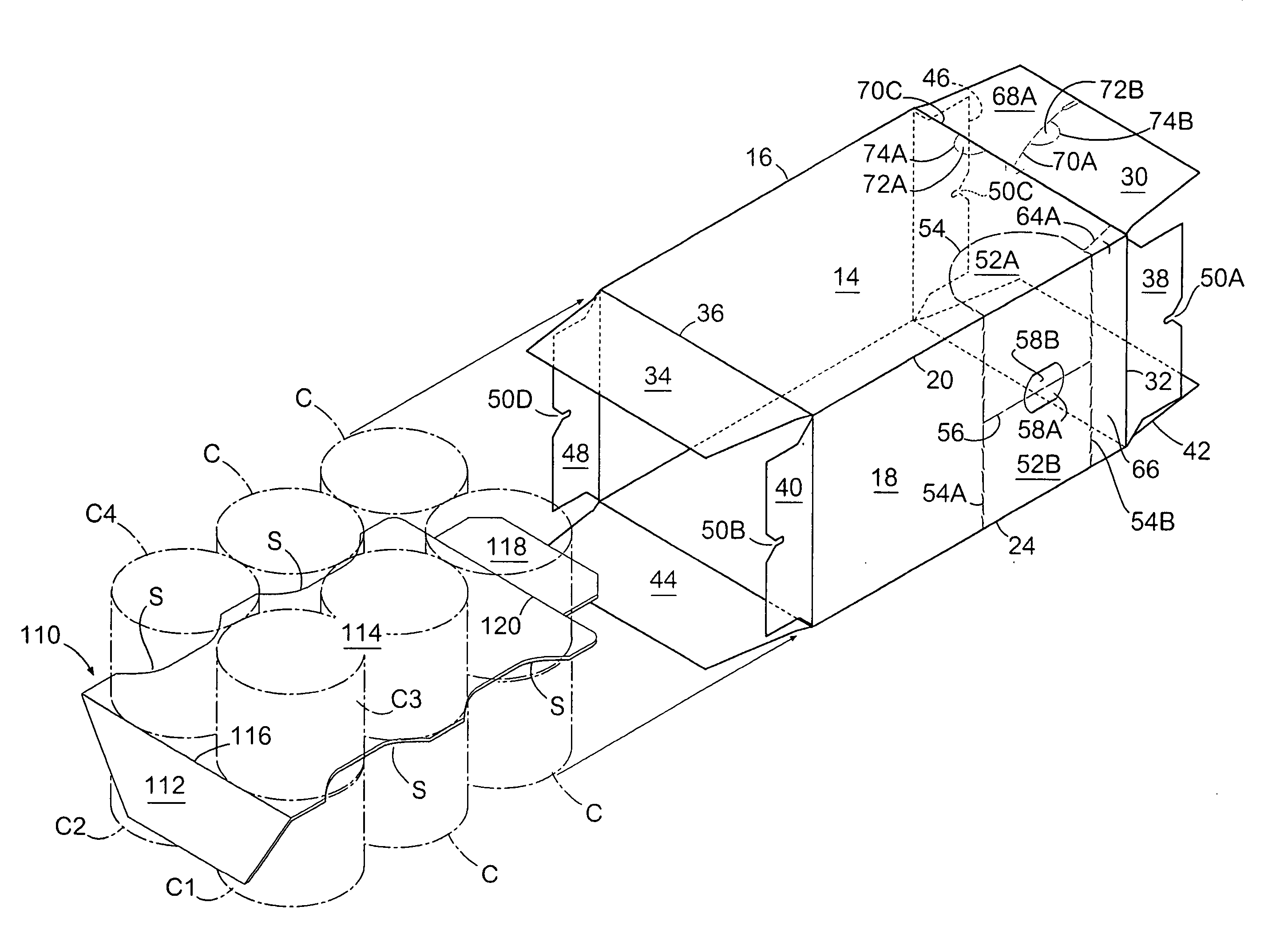
[0026] The present invention is primarily for use with cans of the type used to contain meat products, vegetables and fish. The carton of this invention is primarily useful for cans that are stacked in the carton in two layers with two of more rows in each layer. These cans typically only have a height of two or three inches, and typically these cans are stacked in a carton in two layers of six cans in each layer.

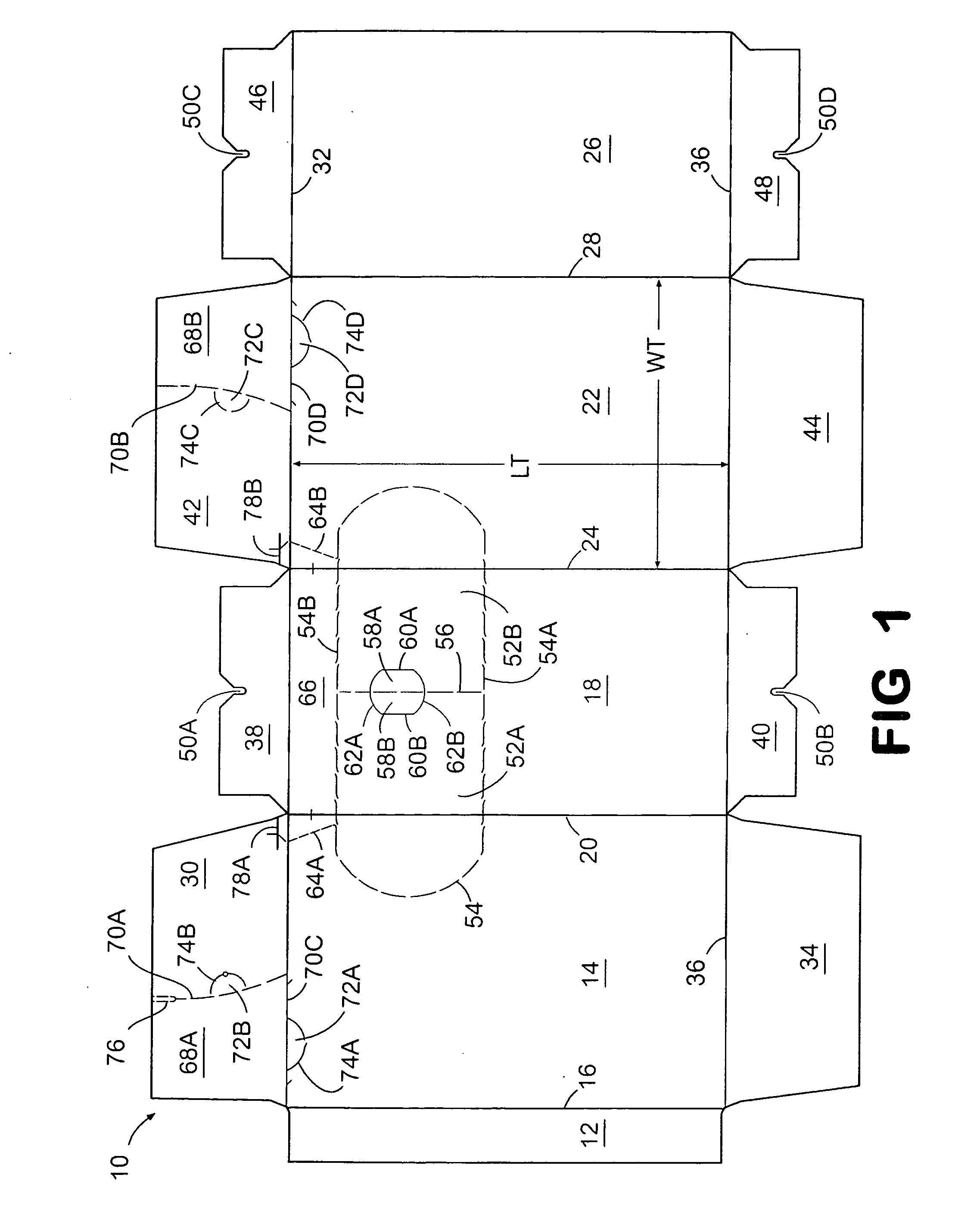
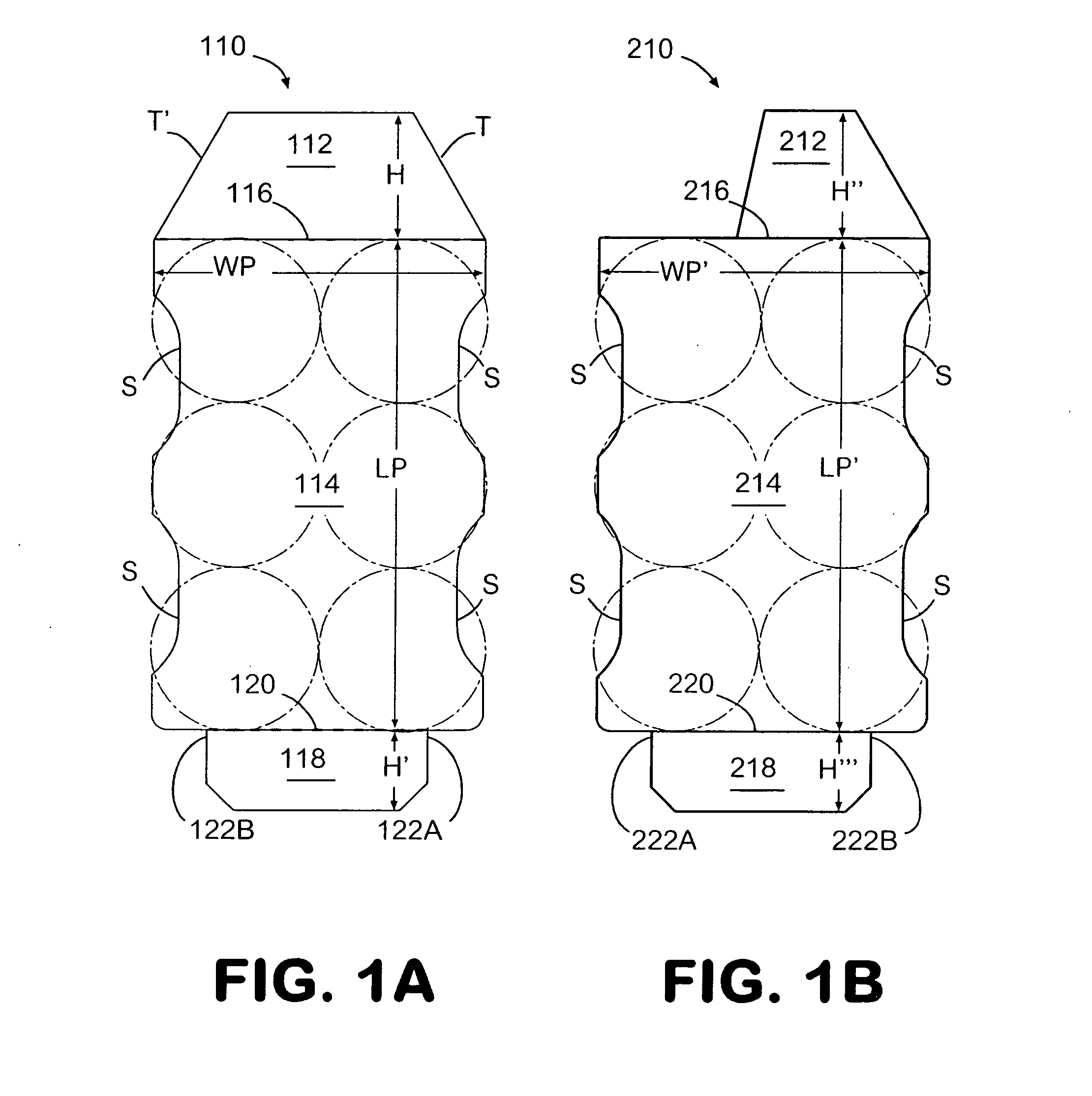
[0027] As illustrated in FIG. 1, the blank 10 for forming the carton of this invention is formed from a foldable sheet of material, such as paperboard. The blanks 110 and 210 for forming the interlocking separator pad is also formed from a foldable sheet of material, such as paperboard, as illustrated in FIGS. 1A and 1B.

[0028] The blank 10 for forming the carton of this invention has a glue flap 12 which is attached to bottom panel 14 by fold line 16 and interconnected to side panel 18 by fold line 20. Side panel 18 is connected to top panel 22 by fold line 24, and interc...


PUM

PropertyMeasurementUnit
heightaaaaaaaaaa
sizesaaaaaaaaaa
distanceaaaaaaaaaa

Abstract

A carton for carrying containers, such as cans, or other articles in two layers which has an interlocking separator pad between the two layers is provided. This separator pad has at least one leading flap which extends through slits provided on the side end flaps on the interlocking end of the carton so that the leading flap is folded up or down and the bottom end flap and top end flap folded and glued to the side end flaps of the carton. This pad may have a trailing flap that is folded up or down on the other end of the carton to assist in holding the pad in position. This pad may have a leading flap on both ends for interlocking both ends of the carton to the interlocking separator pad. This carton may be provided with a dispenser in the side panel near the end on which the carton is rested to dispense cans. This dispenser may extend into the top panel and the bottom panel so that the ends of the cans can be grasped for easy removal. A dispenser may also be provided by forming tears line in the bottom end flap and top end flap that turn and extend along the fold lines between the bottom panel and the top panel until they reach the side panel on which the carton rests for dispensing cans from this dispenser. When this dispenser is used the trailing flap needs to be constructed so it does not extend into the opening formed when the dispenser is opened.

Description

BACKGROUND OF THE INVENTION [0001] 1. Field of the Invention [0002] The present invention relates generally to a carton for carrying cylindrical containers or other types of articles in two layers, with each layer having two or more rows. An interlocking divider pad, or separator pad, is provided which interlocks with the side end flaps on at least one end of the carton. This carton may have a dispenser in the end wall or in a side panel to permit easy access and removal of the containers in the carton. [0003] 2. Background [0004] Fully enclosed cartons that are capable of carrying cans have been used in the past that have a feature for dispensing the cans one at a time. Many of these dispensers do not work in a satisfactory fashion when the cans are carried in two layers. It is desirable to carry cans of certain products in two layers, especially when the can size is small. It would be desirable to have a dispenser that would permit the dispensing of cans from each layer in a carto...

Claims


Application Information

Patent Timeline
Patent Type & Authority Applications(United States)
IPC IPC(8): B65D71/00B65D71/36
CPCB65D71/36B65D2571/00141B65D2571/00728B65D2571/0058B65D2571/0066B65D2571/00401
Inventor HARRELSON, GLEN R.
Owner GRAPHIC PACKAGING INT
Why Eureka
Try Eureka