Display assembly

Inactive Publication Date: 2007-08-07
HESTER THOMAS F
View PDF20 Cites 92 Cited by
  • Summary
  • Abstract
  • Description
  • Claims
  • Application Information

AI Technical Summary

Benefits of technology

[0009]The present invention is directed to improved display assemblies. In accordance with one exemplary embodiment of the present invention, a display assembly is provided for using a folded frame and structural shelf construction. The folded frame is made from corrugated paper and the shelving trays are manufactured from a thin walled plastic. Advantages of the present invention include: a compact shipp

Problems solved by technology

These prior art patents are very limited in their teaching and utilization

Method used


Image

  • Display assembly
  • Display assembly
  • Display assembly

Examples


Embodiment Construction

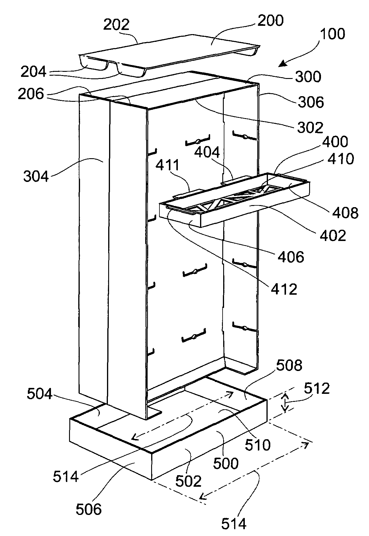
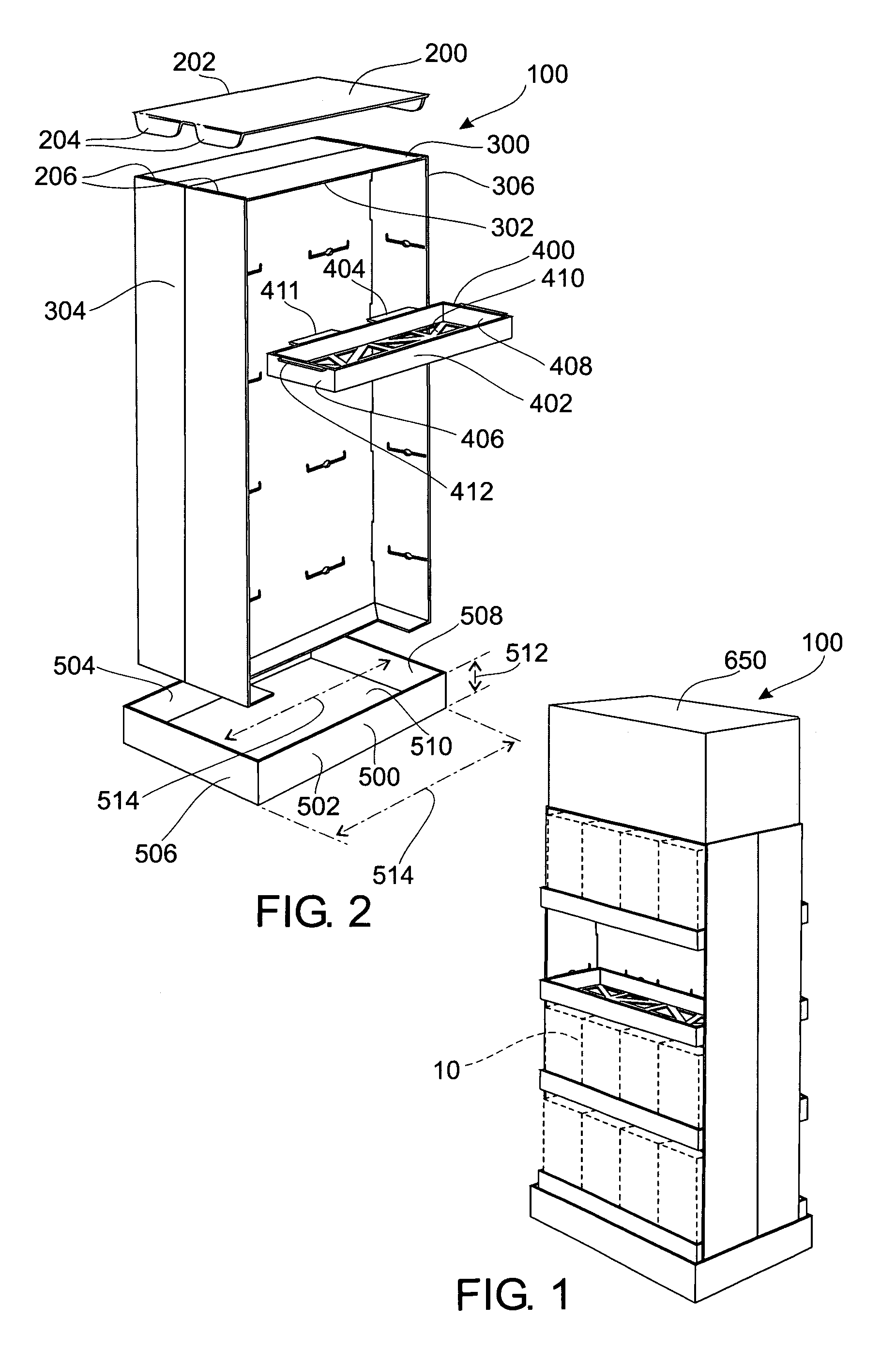
[0031]FIGS. 1, 10, and 12 of the drawings show completed versions of various forms of the display assemblies 100, 349, 801 with graphics on the outer walls of the display assembly 100, 349, 801 for showing products 10. FIGS. 2, 11, and 13 show an exploded view of the various display assemblies 100, 100, 349, 801 showing the components of a display top 200, a display shelf support cabinet 300, a display shelf tray 400, and a display base 500.

[0032]As shown in FIG. 1 of the drawings, one exemplary embodiment of the present invention is generally shown as a front and back display assembly 100 with a display hat 650. FIG. 2 shows an exploded view of the front and back display assembly 100 showing the components of a display top 200, a vertically rising display shelf support cabinet 300, a display shelf tray 400, and a display base 500.

[0033]As shown in FIG. 2, the display top 200 is a planar sheet 202 having locking tabs 204 at each of the corners. The locking tabs 204 are adapted to fi...


PUM


Abstract

A display assembly apparatus and method of assembly using a folded frame and structurally reinforcing shelf for shipping and displaying products. The display uses a planar sheet for compact shipping which is adapted to be folded into the form of a vertically rising cabinet having a vertical supporting member defining shelf apertures which correspond to extending tabs on a shipping tray that allows for product to be shipped in the tray and then directly installed into the cabinet without the problems normally associated with stock transfer from shipping cartons to display areas.

Description

CROSS-REFERENCE TO RELATED APPLICATIONS[0001]This application hereby claims priority to and is a continuation-in-part of U.S. provisional application Ser. No. 60 / 466,984, filed on Apr. 30, 2003 which is hereby incorporated by reference.STATEMENT REGARDING FEDERALLY SPONSORED RESEARCH OR DEVELOPMENT[0002]Not Applicable.REFERENCE TO A MICROFICHE APPENDIX[0003]Not Applicable.BACKGROUND OF THE INVENTION[0004]1. Field of the Invention[0005]The present invention relates to the field of display systems in general. In particular, the present invention relates specifically to a folded panel and tray display system.[0006]2. Description of the Known Art[0007]As will be appreciated by those skilled in the art, a folded corrugated cardboard display may be used to provide a display base for products in a retail or display environment. Details of a typical cardboard display are contained in U.S. Pat. No. U.S. Pat. No. 5,632,390, issued to Podergois on May 27, 1997; U.S. Pat. No. 5,483,779, issued ...

Claims


Application Information

Patent Timeline
IPC IPC(8): A47G29/00
CPCA47F5/116
Inventor HESTER, THOMAS F.
Owner HESTER THOMAS F
Why Eureka
Try Eureka