Single conversion tuner

a single-conversion, tuner technology, applied in the field of single-conversion tuners, can solve the problems of deteriorating image rejection, single-tuned tuneable filters typically do not exhibit sufficient flatness in the pass band, and deteriorating actual image rejection at this frequency, so as to achieve good input sensitivity and image rejection properties, linearity, and high pass band flatness.

a single-conversion, tuner technology, applied in the field of single-conversion tuners, can solve the problems of deteriorating image rejection, single-tuned tuneable filters typically do not exhibit sufficient flatness in the pass band, and deteriorating actual image rejection at this frequency, so as to achieve good input sensitivity and image rejection properties, linearity, and high pass band flatness.

US20060246867A1Active Publication Date: 2006-11-02INTERDIGITAL CE PATENT HLDG

Image

  • Single conversion tuner
  • Single conversion tuner
  • Single conversion tuner

Examples


Embodiment Construction

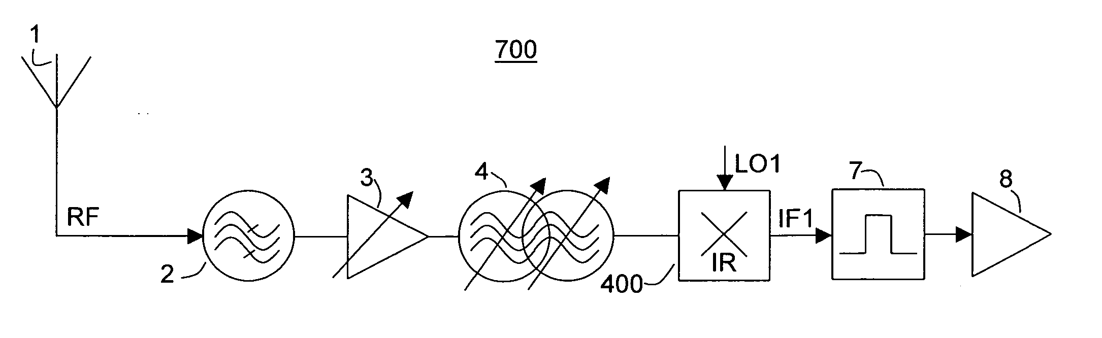
[0036] In FIG. 7 a tuner 700 using an image reject mixer according to an aspect of the invention is presented. In the tuner 700 a radio frequency signal RF is received via an antenna 1. The signal RF received by antenna 1 is coupled to a band select filter 2. From the band select filter 2 the signal is passed-on via a variable gain amplifier 3 to a double-tuned tuneable filter 4. From the double-tuned tuneable filter 4, the signal is coupled to an image reject mixer 400. The image reject mixer 400 is driven by a variable local oscillator signal LO1 and down converts the RF signal to an intermediate frequency signal IF1. The intermediate frequency signal IF1 is further fed to an SAW filter 7 for channel separation. An amplifier 8 receives the filtered signal IF1 and buffers it for further processing.

[0037] The advantages which result from the inventive tuner circuit 700 will now be described with reference to FIGS. 8 to 10.

[0038] In FIG. 8 the attenuation versus frequency for a dou...


PUM


Abstract

A single conversion tuner suitable for receiving RF signals having different requirements as to selectivity, linearity and image rejection is presented. Tuners of this kind are particularly useful for digital terrestrial as well as cable reception, where different modulation schemes require very high image rejection ratios on one hand and high linearity or pass band flatness on the other hand. The inventive tuner features a double-tuned tuneable filter in combination with an image reject mixer. The double-tuned filter provides excellent pass band flatness, while the image reject mixer provides a high intrinsic image rejection. The image rejection ratio of the combination of image reject mixer and tuneable filter is very high and fulfils the requirements of commonly used modulation schemes such as 8VSB, while the pass band flatness is compliant with the requirements for modulation schemes such as QAM.

Description

FIELD OF THE INVENTION [0001] The invention relates to a tuner for receiving modulated RF signals. In particular, the invention relates to a television receiver including a tuner for receiving modulated RF signals. BACKGROUND OF THE INVENTION [0002] Television signals are transmitted at radio frequencies (RF) using terrestrial, cable, or satellite transmission schemes. Terrestrial and cable TV signals are typically transmitted at frequencies of approximately 57 to 860 MHz, with 6 MHz channel spacings. Satellite TV signals are typically transmitted at frequencies of approximately 980 to 2180 MHz. [0003] Modern television receivers may receive the transmissions directly from antenna or from cable networks. More recently the transmissions are modulated so as to transport digital signals representing audio and video signals of a programme. When digital signals are transmitted, different modulation schemes are used for transmissions to be received directly from antenna, so called off-air...

Claims


Application Information

Patent Timeline
02 Nov 2006
Publication
US20060246867A1
IPC
H04B1/10; H03D7/00; H03D7/18; H03J3/26; H04N5/44; H04N5/455
CPC
H03J3/26; H03J2200/14; H04N5/4446; H04B1/406; H04B1/26
Inventors
ARMBRUSTER, VEIT; SELZ, ALFRED