Accessory gearbox

a gearbox and accessory technology, applied in the direction of machines/engines, sustainable transportation, climate sustainability, etc., can solve the problems of reducing engine fuel efficiency, reducing engine weight and complexity, and difficulty for maintenance personnel during diagnostic and repair procedures, so as to reduce engine weight and complexity and improve engine fuel burn

Inactive Publication Date: 2006-11-09
RAYTHEON TECH CORP
View PDF11 Cites 181 Cited by
  • Summary
  • Abstract
  • Description
  • Claims
  • Application Information

AI Technical Summary

Benefits of technology

[0009] Provided is an accessory gearbox for a gas turbine engine that contributes minimally to engine weight and complexity while improving engine fuel burn. An accessory gearbox, in accordance with the current invention, comprises a stationary frame that is circumferentially disposed about a central longitudinal axis of the engine. The frame includes a forward-directed axial face and a rearward-directed axial face for fastening the frame to the engine. A central bore accepts a rotational driving means and an outermost rim circumscribes the outer diameter of the frame. A compartment is located between the bore and the rim. At least one primary accessory is mounted to a face and proximate the compartment, remotely engaging the driving means and able to be driven concurrently therewith.
[0010] Since the inventive accessory gearbox is integrated into an engine frame, there is no need for an extended tower shaft with mid-span bearing, angle gearbox housing, lay shaft or accessory gearbox housing. The elimination of these components from beneath the engine or fan case contributes minimally to engine weight and provides additional area for housing pipes, wires and brackets in order to simplify engine maintenance. A reduction in both engine flexure and frontal area also improves engine fuel burn.

Problems solved by technology

The requirement for an angle gearbox housing, lay shaft and accessory gearbox housing adds substantial weight and complexity to the engine.
Accessory gearboxes mounted beneath the engine also contribute to engine flexure, which is known to negatively affect compressor and turbine clearances and thus reduces engine fuel efficiency.
The inaccessibility of the gearbox causes difficulties for maintenance personnel during diagnostic and repair procedures.
The requirement for an angle gearbox housing and extended tower shaft with a mid-span bearing adds substantial weight and complexity to the engine.
Also, accessory gearboxes mounted beneath the fan case increase the frontal area of the engine, increasing the aircraft drag and thus increasing the engine fuel burn.

Method used


Image

  • Accessory gearbox
  • Accessory gearbox
  • Accessory gearbox

Examples


Embodiment Construction

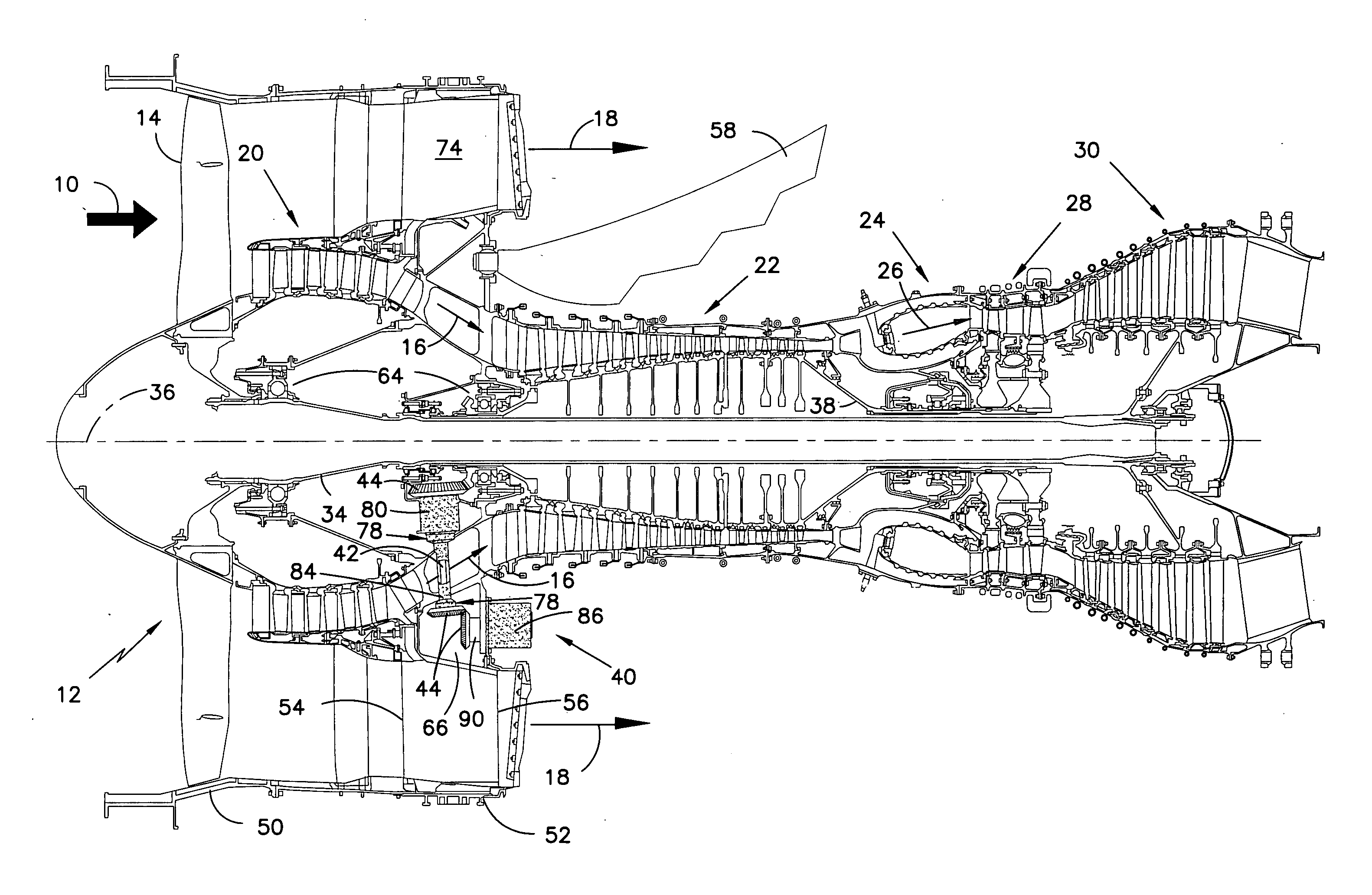
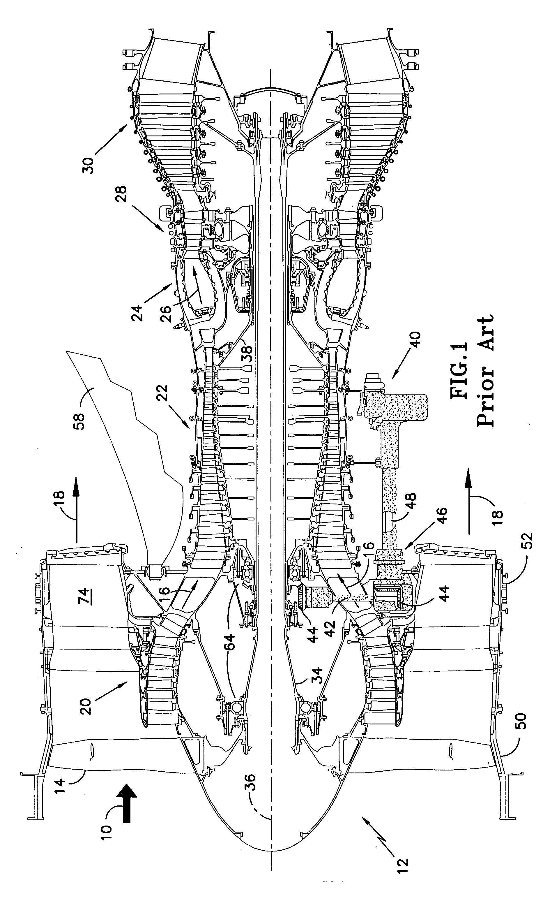
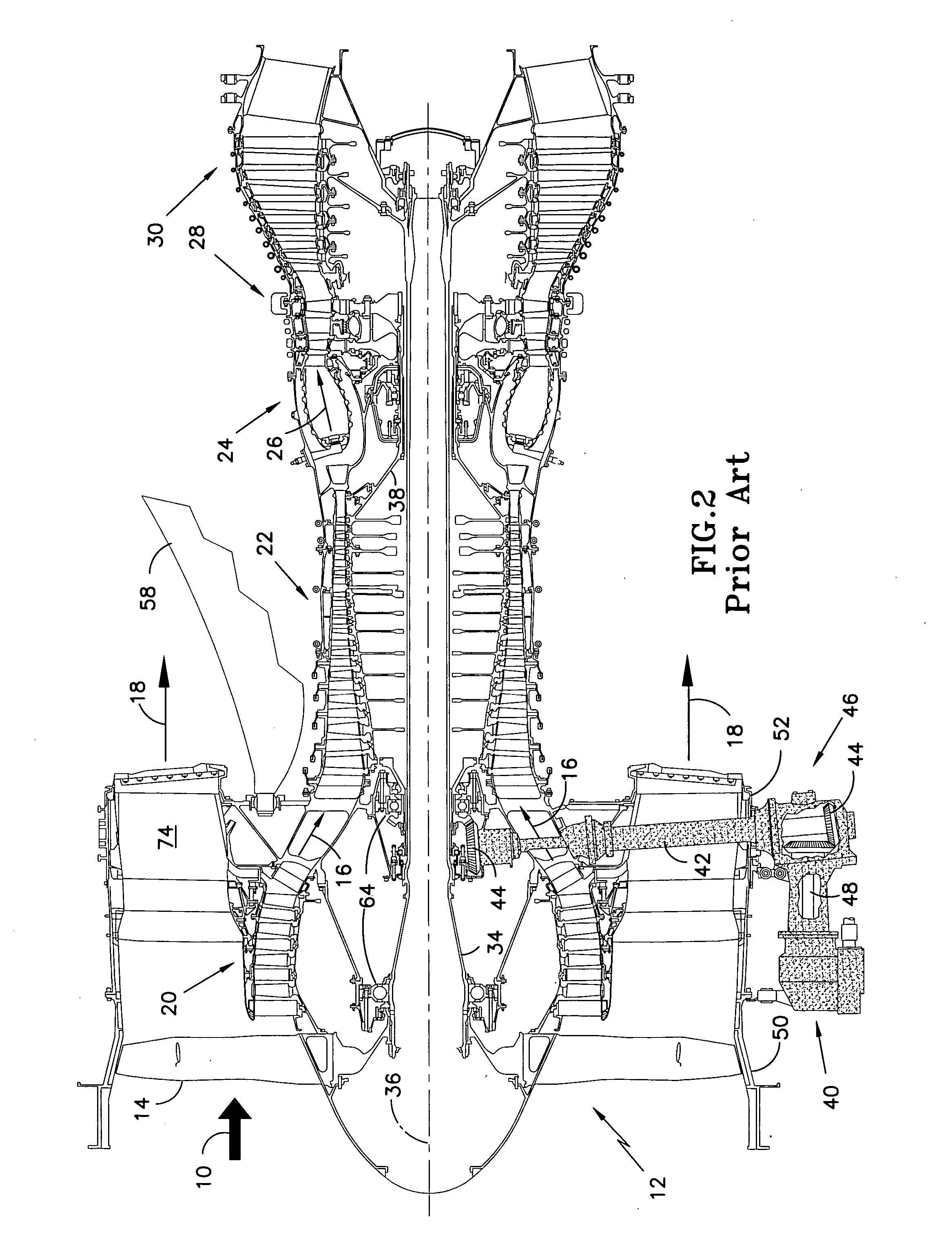
[0020] Referring first to FIGS. 1, 2 and 3, air 10 enters a gas turbine engine 12 via a forward mounted fan 14, where the air 10 is directed into two discrete streams: a core air stream 16 and a bypass air stream 18. The core air 16 is pressurized in series by a low-pressure compressor 20 and a high-pressure compressor 22, before being mixed with fuel and burned in a centrally mounted combustor 24. The core air 16 exits the combustor 24 as combustion gases 26, which expand in series through a high-pressure turbine 28 and then a low-pressure turbine 30 before being exhausted from the engine 12. The bypass air 18 is directed-outside the engine 12 through one or more bypass ducts 32 (not shown). The exhausting combustion gases 26 in combination with the bypass air 18 generate a forward propulsive thrust. The low-pressure turbine 28 drives the low-pressure compressor 20 via a low rotor shaft 34 revolving about a central, longitudinal axis 36 of the engine 12. Similarly, the high-pressur...


PUM


Abstract

Provided is an accessory gearbox for a gas turbine engine that contributes minimally to engine weight and complexity. An accessory gearbox comprises a stationary frame that is circumferentially disposed about a central longitudinal axis of the engine. The frame includes a forward-directed axial face and a rearward-directed axial face for fastening the frame to the engine. A central bore accepts a rotational driving means and an outermost rim circumscribes the outer diameter of the frame. A compartment is located between the bore and the rim. At least one primary accessory is mounted to a face and proximate the compartment, remotely engaging the driving means and able to be driven concurrently therewith.

Description

BACKGROUND OF THE INVENTION [0001] (1) Field of the Invention [0002] The invention relates to an accessory gearbox and more specifically to an accessory gearbox integrated with a stationary frame of a gas turbine engine. [0003] (2) Description of the Related Art [0004] In an axial-flow gas turbine engine, incoming air is directed rearward by a large diameter fan, where the air is typically split into two discrete streams: a core air stream and a bypass air stream. The core air stream enters the engine and is pressurized in series by one or more rotating compressors and is then mixed with fuel in a central combustor. The fuel and air mixture is burned in and expelled from the combustor as hot combustion gases. The hot combustion gases are directed rearward to one or more turbines disposed downstream of the combustor. The turbines extract power from the combustion gases and use the power to rotate the compressors via a common rotor shaft or rotor spool. Conversely, the bypass air stre...

Claims


Application Information

Patent Timeline
Patent Type & Authority Applications(United States)
IPC IPC(8): F02C6/00
CPCF02C7/32Y10S74/05Y02T50/671F02C7/36Y02T50/60
Inventor SUCIU, GABRIELMERRY, BRIAN
Owner RAYTHEON TECH CORP
Why Eureka
Try Eureka