
Cleaning of system for dispensing of liquid droplets
a technology for liquid droplets and dispensing systems, which is applied in the direction of immunoassays, instruments, material testing goods, etc., can solve the problems of contamination of the proportion of dispensing systems, and achieve the effects of short washing cycle, enhanced instrument productivity, and reduced carryover
- Summary
- Abstract
- Description
- Claims
- Application Information
AI Technical Summary
Benefits of technology
Problems solved by technology
Method used
Image

Examples
Embodiment Construction
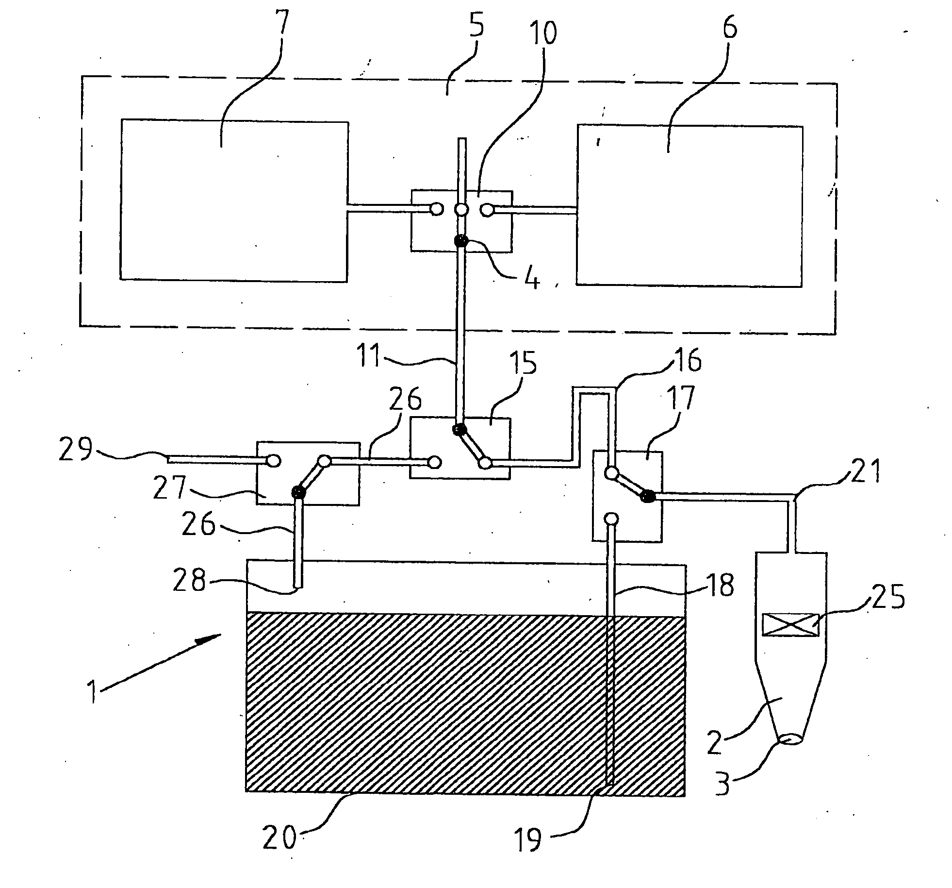
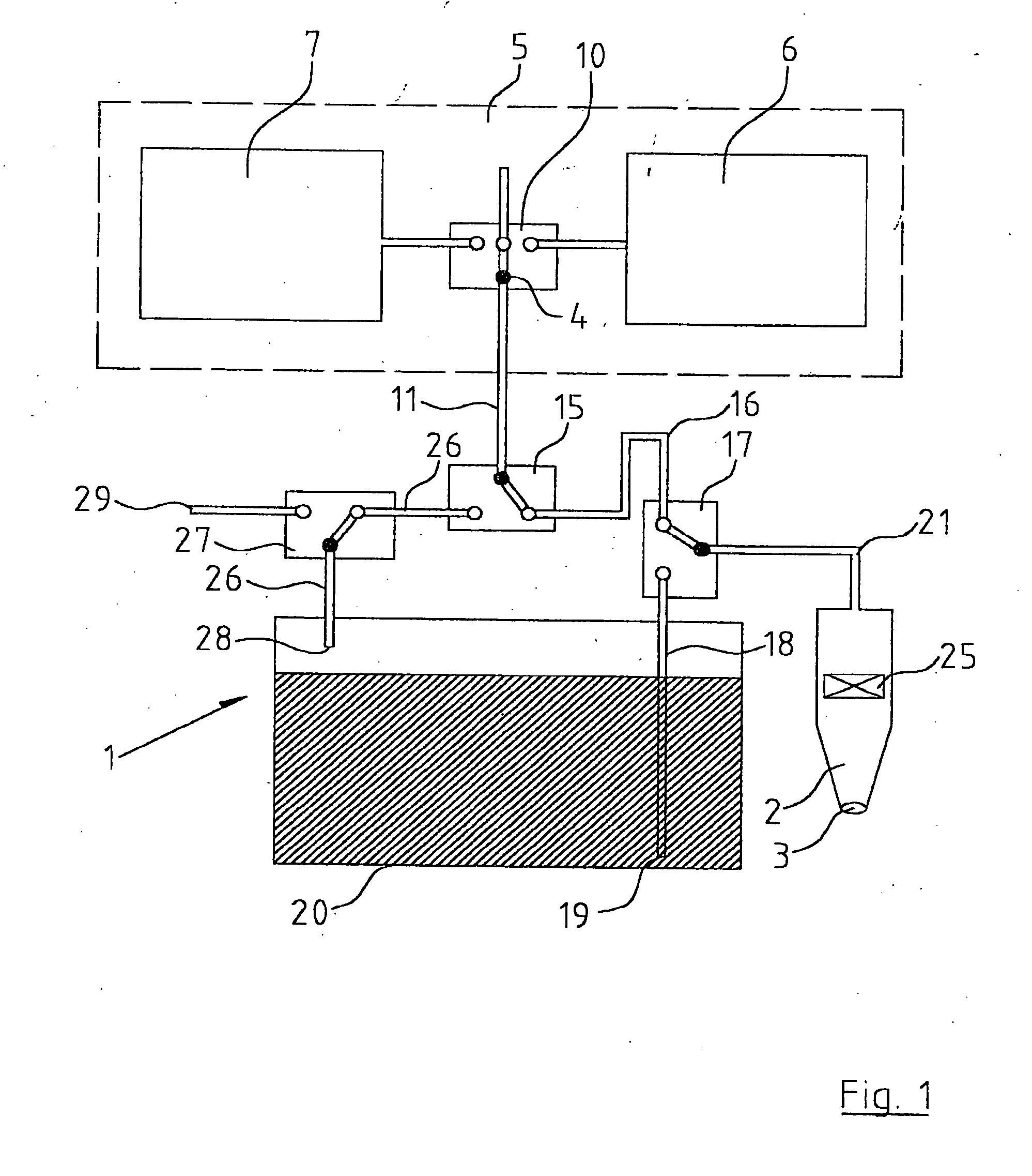
[0029]FIG. 1 shows a dispensing assembly for dispensing and aspiration of low volumes of liquids, indicated generally by the reference numeral 1, hereinafter, for brevity, the system 1. The system 1 has a dispensing tip 2 terminating in a nozzle 3 that can be connected to an output 4 of a pneumatic source 5 delineated by interrupted lines. The pneumatic source 5 comprises a pressure source 6 and a vacuum source 7 provided by a compressor, not shown. The pneumatic source 5 connects the pressure source 6 and vacuum source 7 via a switching valve 10 to a conduit 11. The conduit 11 in turn feeds, via a switching valve 15, a pneumatic line 16 which in turn feeds a valve 17. The valve 17 is connected to a liquid feed line 18 terminating at an inlet 19 mounted in a cleaning liquid tank or flush bottle 20. The valve 17 also feeds a pneumatic line 21 connected to the dispensing tip 2.
[0030] The dispensing tip 2 houses a valve 25. The valve 15 is also connected to a further pressurising line...
PUM
 Abstract
Description
Claims
Application Information