Liquid sample dispensing methods for precisely delivering liquids without crossover

a liquid sample and liquid technology, applied in the field of liquid sample dispensing, can solve the problems of intra-sample carryover or contamination of reusable probes used to deliver liquid aliquots from successive containers such as tubes or liquid reagent vessels, and the liquid tends to remain on the exterior surface of the pipette, so as to reduce the amount of aspirated liquid. , the effect of minimizing the amount of aspirated liquid

Inactive Publication Date: 2007-05-01
SIEMENS HEALTHCARE DIAGNOSTICS INC
View PDF15 Cites 0 Cited by
  • Summary
  • Abstract
  • Description
  • Claims
  • Application Information

AI Technical Summary

Benefits of technology

[0017]The principal object of the invention is to provide a method for using a sampling pipette that substantially reduces carryover between samples aspirated by the pipette and that is simultaneously adapted to precisely deliver an amount of liquid from a first liquid source container to a first liquid target container. An important aspect of the invention is to provide a sampling pipette in which any liquid within the target container is displaced away from the proximate vicinity of the sampling pipette by axially spinning the target container.
[0018]By spinning the target container, liquid therein is moved to inner walls and away from the central portion thereof; consequently, the sampling pipette may be lowered into the target container a sufficient distance to bring a droplet of liquid at the nozzle of the sampling pipette into contact with the bottom of the target container. Physically toughing the droplet with the bottom of the target container releases surface tension energy so that the droplet cleanly flows into the target container without contacting the sampling pipette with any liquid spun against the walls of the target container. Carryover of liquid aspirated and dispensed by the pipette may thereby be minimized between the first source container, the first target container and any subsequently accessed source and target containers.
[0019]A further aspect of the invention relates to dispensing a droplet from the sampling pipette in a first step in which a larger portion of the droplet is dispensed into a target container, optionally using the above described method for minimizing carryover of aspirated and dispensed liquids, and the smaller portion is retained within the sampling pipette. After the larger droplet is dispensed, liquid within the target container is displaced away from the proximate vicinity of the sampling pipette by axially spinning the target container, the sampling pipette is lowered into the target container to bring the smaller portion droplet of liquid into contact with the bottom of the target container so that the entire remaining smaller droplet is dispensed. Sensing to confirm the “touching-off” of this smaller droplet assures that the total volume of liquid dispensed in the two steps is bounded at a maximum by the originally aspirated volume and at a minimum by the volume of liquid dispensed in the first step alone.
[0020]Briefly summarized, the invention provides a method for reducing carryover of and precisely delivering liquid from a source container to first and subsequent target containers by spinning the target containers so that any liquid within the target container is removed from the dispensing means.

Problems solved by technology

Conventional pipettes suffer the disadvantage that liquid tends to remain on the exterior surface of the pipette when the pipette is withdrawn after aspiration.
In either case, the volume of liquid received by the vessel is altered in an unpredictable fashion.
Another disadvantage is that reusable probes used to deliver liquid aliquots from successive containers such as tubes or liquid reagent vessels are a source of intra-sample carryover or contamination.
However, disposable pipettes are costly and over a long period of time, become an unexpectedly high item of unwanted expense.
However, wiping is an extra potential source of contamination, and also introduces additional automated mechanisms that lower the throughput rate and increase the expense of an analyzer.
Wash chambers can leak fluid and also can channel along only one side or a portion of the pipette which can leave residue on the pipette exterior.
Additionally, if a last drop of wash diluent does not drop off the pipette and is carried back to an aspiration vessel, the droplets dilute the sample or reagent, introducing unwanted sources of error.
Such aspiration, however, introduces the possibility of drawing the unwanted carry-over contaminants deeper into the tubing and apparatus which comprises the sampling system.
From this discussion of the art state in automated microbiological analyzers, it may be seen that while there has been considerable effort made toward the problem associated with minimizing contamination and carry-over between samples, there remains an unmet need for a simplified system to address the related problems of precisely delivering an amount of liquid from a sample or reagent container to a reaction tube and for reducing carry-over of liquid from one reaction tube to the next.

Method used


Image

  • Liquid sample dispensing methods for precisely delivering liquids without crossover
  • Liquid sample dispensing methods for precisely delivering liquids without crossover
  • Liquid sample dispensing methods for precisely delivering liquids without crossover

Examples


Embodiment Construction

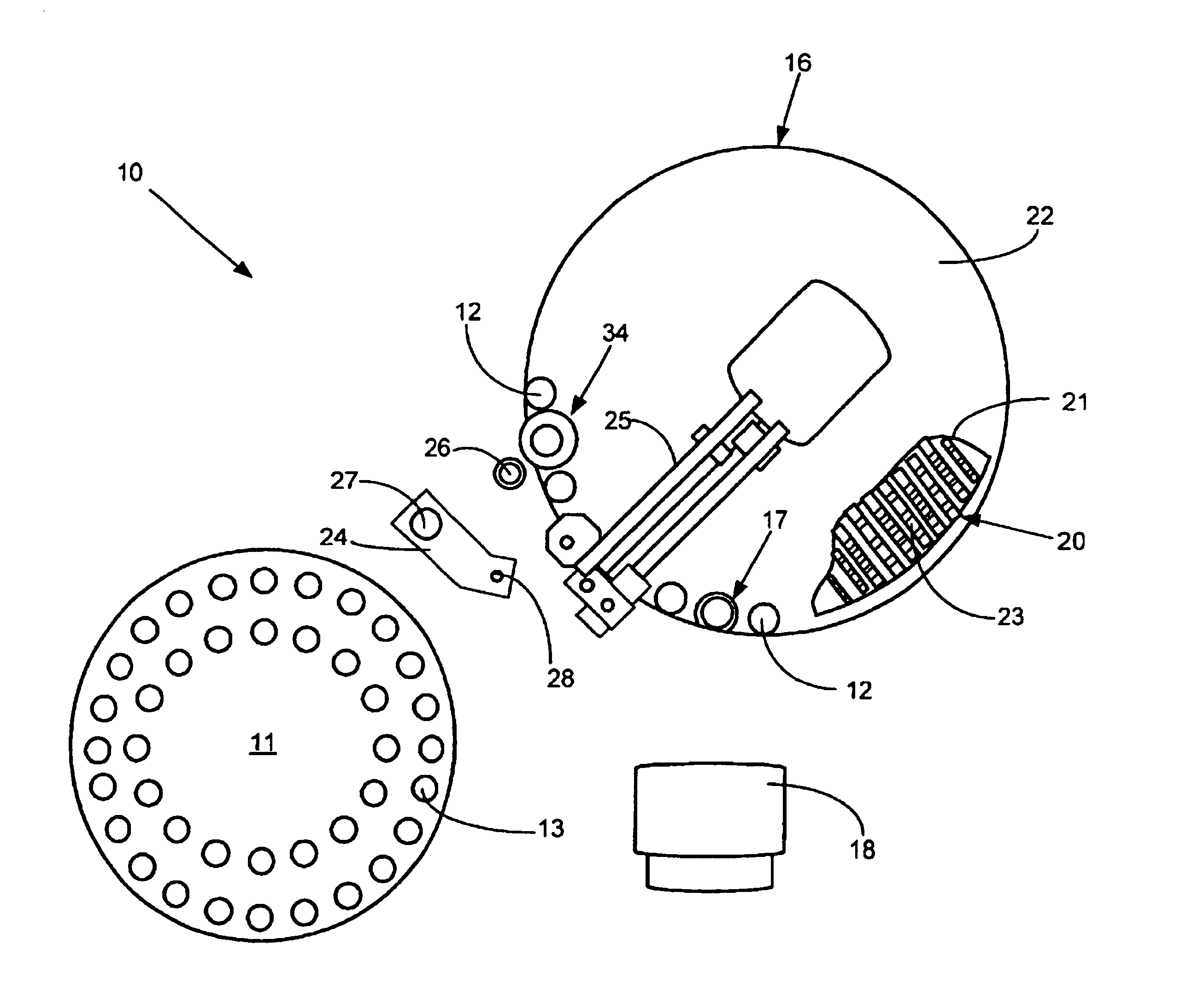
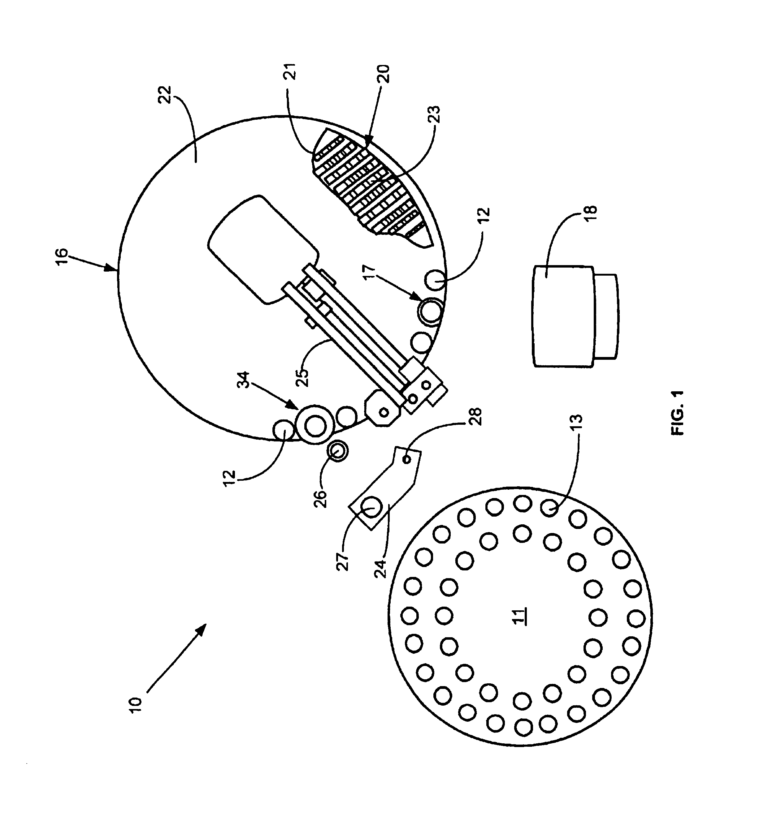
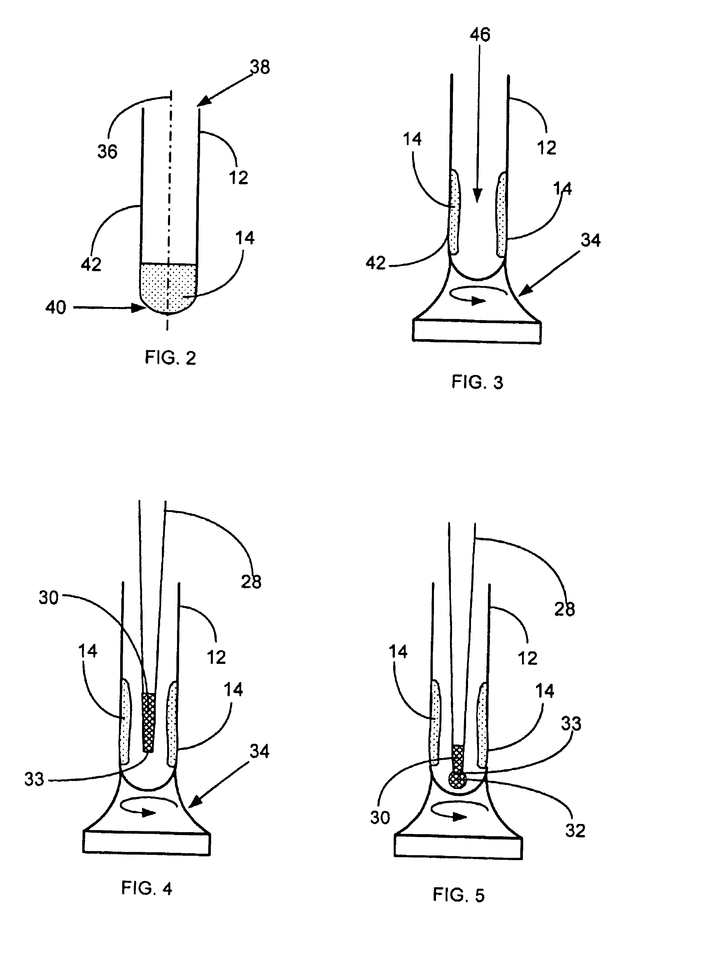
[0026]The method and apparatus of this invention will be described initially with particular reference to FIG. 1 of the drawings. FIG. 1 shows schematically the elements of a conventional automatic chemical analyzer 10 comprising a sample cup carousel 11 supporting a plurality of open sample tubes 13, a test vessel carousel 14, adapted to hold a plurality of test vessels 12 and to provide plurality of reagent liquid cartridges 20, illustrated as disposed beneath a cut out portion 21 of a lid 22, which covers various thermally controlled compartments. The vessel carousel 14, preferably in the form of a wheel, has about one hundred separate open cavities 17 for holding vessels 12, the inner wall of each cavity having an opening to allow transmission of light. Vessels 12 are seen in FIG. 2 as having a generally cylindrically shape around a central axis 36, also having an open top 38 and a closed bottom 40. Test vessel carousel 14 is provided with means 34 for rotating selected ones of ...


PUM

PropertyMeasurementUnit
distanceaaaaaaaaaa
volumeaaaaaaaaaa
pressureaaaaaaaaaa

Abstract

A method for reducing carryover of and delivering liquid taken from a source container by a dispensing means to a target container by spinning the target container so that any liquid within the target container is removed from the dispensing means prior to dispensing liquid into the target container.

Description

FIELD OF THE INVENTION[0001]The present invention relates to liquid sample dispensing in which a sampling pipette aspirates liquids from a sample or reagent container and dispenses the aspirated liquid into a reaction vessel. More particularly, the invention relates to a system for precisely delivering an amount of liquid from a sample or reagent container into a reaction tube and for reducing carry-over of liquid from one reaction tube to the next, thereby protecting the integrity of the solution within the reaction tube.BACKGROUND OF THE INVENTION[0002]Various types of tests related to patient diagnosis and therapy can be performed by analysis of a sample of a patient's infections, bodily fluids or abscesses. Such samples are typically placed in sample vials, extracted from the vials, combined with various reagents in special reaction vessels or tubes, incubated, and analyzed to aid in treatment of the patient. Automated clinical analyzers adapted to perform these operations typic...

Claims


Application Information

Patent Timeline
Patent Type & Authority Patents(United States)
IPC IPC(8): B65B1/04B01L9/00B01L99/00G01N35/10
CPCB01L3/0293G01N35/1016B01L9/00Y10T436/11G01N2035/1034Y10T436/2575
Inventor DEVLIN, SR., WILLIAM JACKSON
Owner SIEMENS HEALTHCARE DIAGNOSTICS INC
Why Eureka
Try Eureka