Stent holder having a reduced profile

a technology of stent holders and holder plates, applied in the field of implantable medical devices, can solve the problems of limited number of commercially available, unfavorable efficient product development management, and significant testing tim

Active Publication Date: 2016-10-04
ABBOTT CARDIOVASCULAR
View PDF46 Cites 0 Cited by
  • Summary
  • Abstract
  • Description
  • Claims
  • Application Information

AI Technical Summary

Benefits of technology

[0009]The holder includes a narrow cross section or flow profile. In a preferred embodiment there is a triangle-shaped base and triangle-like and movable retainer (sized to receive a DES) that significantly reduces impedance of a free flow of release media to thereby expose interior or hidden surfaces, e.g., side and luminal surfaces or surfaces close to the holder supporting surfaces of a DES, during a real-time or an accelerated drug release test. The resulting free flow of release media to both interior and exterior surfaces will result in more reproducible and reliable drug release profile results.
[0010]A preferred holder includes a shouldered design to better assure that a DES remains securely in place while letting release media freely drain off the holder when changing to a next dip interval. This shouldered feature can enhance the accuracy and precision of the drug release determination by minimizing carryover. The holder can also be used with a wide variety of DES sizes, both in length and diameter, as compared to existing holders, without detracting from the desirable low or minimal profile features.
[0011]This preferred holder, which may be used with either a drug-eluting stent or scaffold, has two separable parts. The first part is a core wire with one end shaped as an isosceles or equilateral triangle (in two possible base widths of about 8 to 9 mm and about 12 to 13 mm for different outer diameter sizes of stents). The triangle shape (isosceles or equilateral) end of the core wire helps with stable seating of the stent at one end of the holder. The core wire can be in different lengths for different lengths of the stent.
[0012]The second part is a metallic retainer, which slides over the core wire and brackets the stent so that the stent is held between the triangular-shaped end of the core wire and the retainer, thereby stabilizing the stent in place. The retainer has a flat surface (in two widths of about 8 to 9 mm and about 12 to 13 mm as needed for different stent diameter sizes). It also has a thin frontal profile of about 2 to 3 mm for both width sizes.
[0013]The retainer also has a collar that discourages sliding movement along the wire during dipping yet provides very little increase in frontal profile or surfaces to interfere with the flow of release media or retention of the media when the holder is removed from the test container (thereby avoiding contamination with subsequent testing). Such a collar is sufficient to keep the retainer in its manually-positioned placed during the dipping of the stent and holder in a test container holding the release medium.

Problems solved by technology

Most notably, when evaluating the sustained release of a candidate DES structure the test can consume significant time, spanning weeks or months for sustained release of these dosage forms.
This is disadvantageous in early research, and therefore not conducive for efficient management of product development.
There are, however, only a limited number of commercially available Apparatus 7 sample holder designs to accommodate a wide variety of drug / device configurations.
As a result, companies often design and build custom sample holders to suit specific needs since commercially available choices have limited usefulness.
The design types in FIGS. 1A and 1B do not, generally speaking, produce an optimal flow profile of release medium over drug-containing surfaces of a medical device during the drug release testing, especially in the case of a stent with both exterior and interior surfaces coated.
As a result, it was concluded that the known Apparatus 7-type holders tend to cause significant variability in the amount of drug released at each dipping time point, compromising the precision and accuracy of the test.

Method used


Image

  • Stent holder having a reduced profile
  • Stent holder having a reduced profile
  • Stent holder having a reduced profile

Examples


Embodiment Construction

[0044]For purposes of this disclosure, the following terms and definitions apply:

[0045]The term “about” means 20%, 15%, 10%, 5%, 4%, 3%, 2%, 1.5%, 1%, between 1-2%, 1-3%, 1-5%, or 0.5%-5% less or more than, less than, or more than a stated value, a range or each endpoint of a stated range, or a one-sigma, two-sigma, three-sigma variation from a stated mean or expected value (Gaussian distribution). It is understood that any numerical value, range, or either range endpoint (including, e.g., “about none”, “about all”, etc.) preceded by the word “about” in this disclosure also describes or discloses the same numerical value, range, or either range endpoint not preceded by the word “about”.

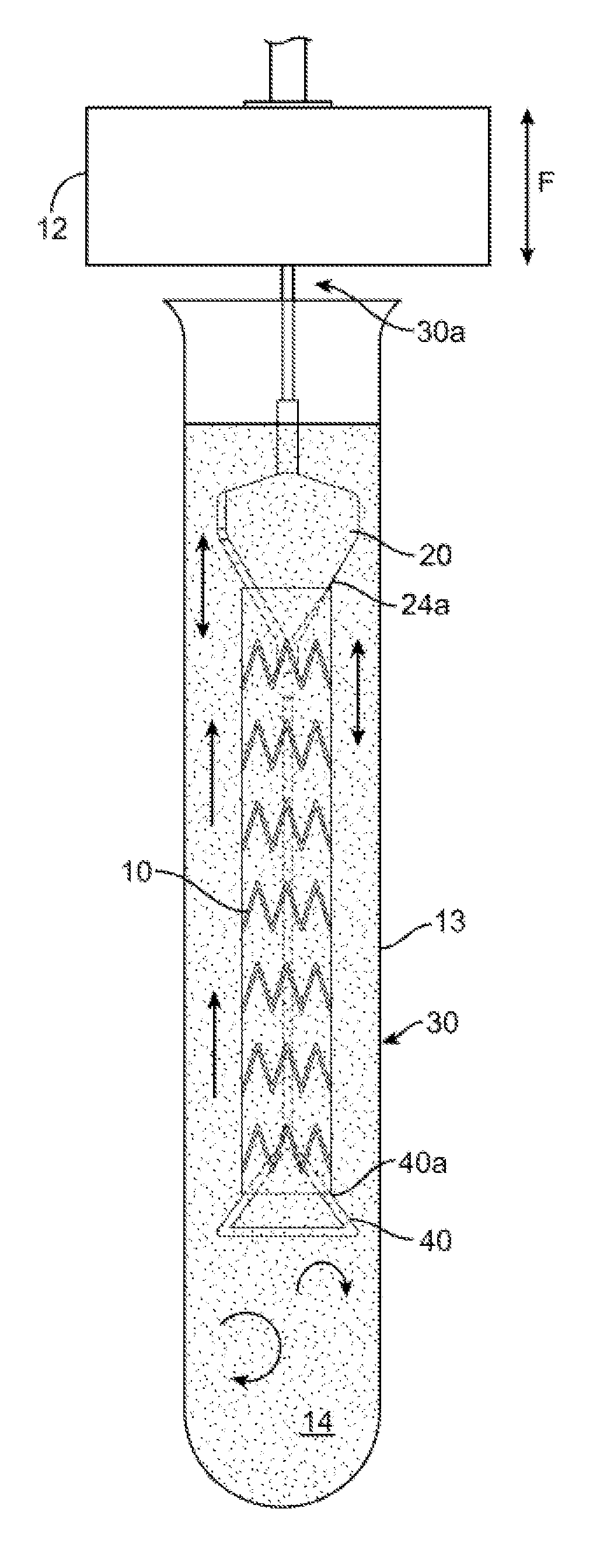
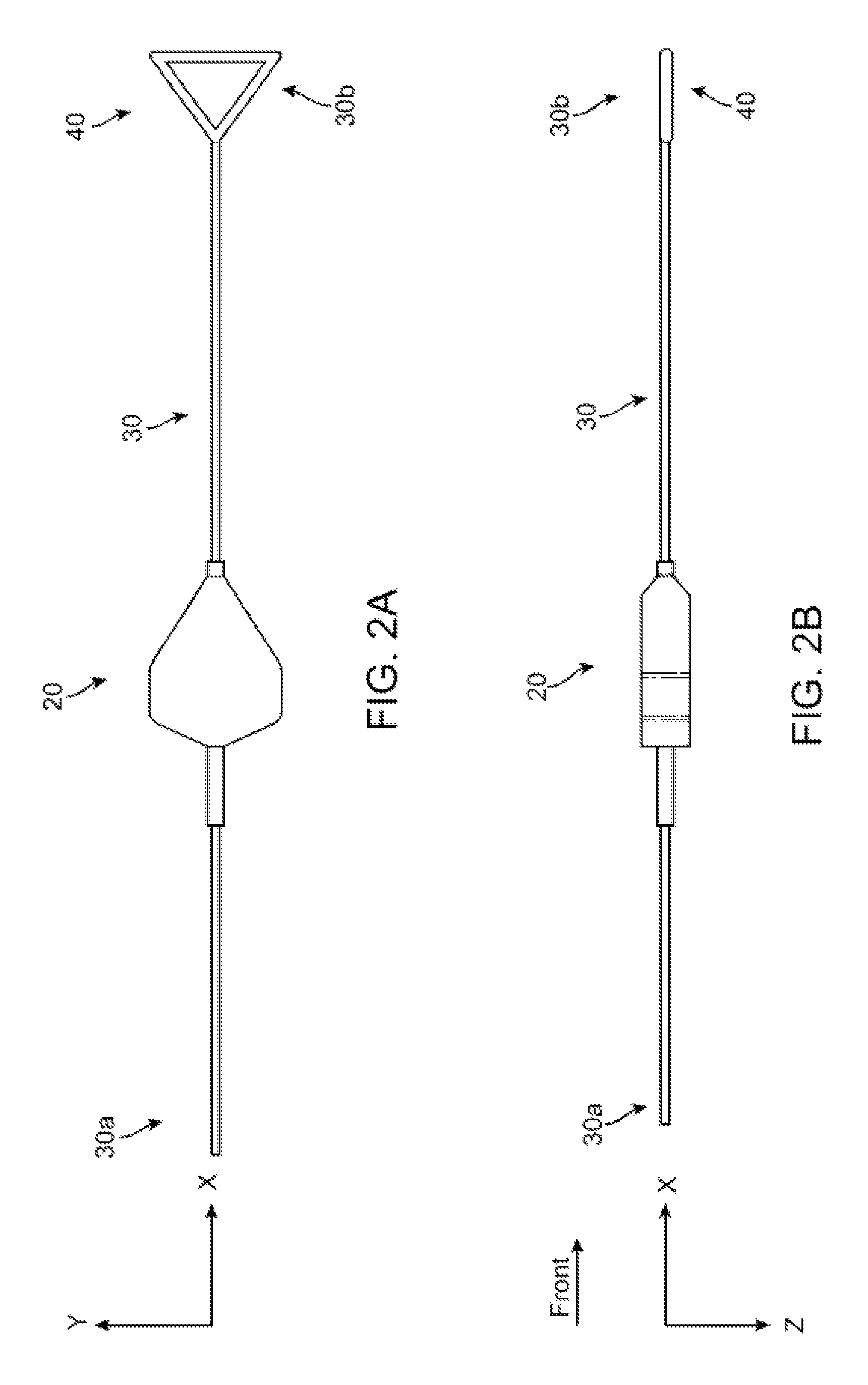
[0046]FIGS. 2A-2B show side and top views of a stent holder according to the disclosure. The stent holder includes a retainer 20 separable and capable of being forcibly slid along a mandrel, which in this example is a wire 30. The wire 30 has a first end 30b that receives the retainer 20 and a second ...


PUM

PropertyMeasurementUnit
outer diameter sizesaaaaaaaaaa
diameteraaaaaaaaaa

Abstract

A stent holder for securely holding a drug eluting stent (DES) during a real-time or an accelerated in-vitro drug release test of a therapeutic substance contained in or on the DES. The holder has a retainer portion and a wire portion separable from the retainer. The holder has a narrowed or reduced profile resulting in less disruptive flow in and around the stent during the accelerated in-vitro drug release test.

Description

FIELD OF THE INVENTION[0001]The present invention relates to implantable medical devices and more particularly medical device holders used during the real-time or accelerated drug-release testing.BACKGROUND OF THE INVENTION[0002]The localized drug delivery from a drug-eluting stent (DES) has been shown to be quite effective and accepted as one of the most promising treatment methods for preventing restenosis after stenting procedures. For example, a polymeric coating on a DES is designed to sustain appropriate drug release kinetics in order to deliver the therapeutic dose of the drug for the required time interval at the treatment site. An estimation of the real-time release rate is critical for characterization of the DES dosage forms.[0003]With respect to testing drug elution properties of a DES, there are certain challenges to overcome. Most notably, when evaluating the sustained release of a candidate DES structure the test can consume significant time, spanning weeks or months ...

Claims


Application Information

Patent Timeline
Patent Type & Authority Patents(United States)
IPC IPC(8): A61F2/95G01N13/00G01N33/15
CPCG01N13/00A61F2/95A61F2250/0067B01L2300/0609G01N33/15G01N2013/006
Inventor HAGHIGHAT-KHANSARI, KIARASHPINSON, DAVIDKAMBERI, MARIKA
Owner ABBOTT CARDIOVASCULAR
Why Eureka
Try Eureka