Laminate flooring panel bevel and method of manufacturing same

a technology of laminate flooring and bevels, which is applied in the field of laminate flooring, can solve the problems of incongruous bevels, time-consuming operation, and the inability of adjoining laminate flooring pieces to match the bevels

Inactive Publication Date: 2006-11-23
QUALITY CRAFT
View PDF0 Cites 68 Cited by
  • Summary
  • Abstract
  • Description
  • Claims
  • Application Information

AI Technical Summary

Problems solved by technology

However, the removal of material of the laminate flooring thereafter required a further operation to apply the decorative layer and the cover over the decorative layer to the beveled edge previously planed.
This operation is tedious and time consuming.
While this process facilitated the beveled edge manufacturing operation, the pressing operation was inconsistent with the result that adjoining pieces of laminate flooring might not have matching beveled edges.

Method used


Image

  • Laminate flooring panel bevel and method of manufacturing same
  • Laminate flooring panel bevel and method of manufacturing same
  • Laminate flooring panel bevel and method of manufacturing same

Examples


Embodiment Construction

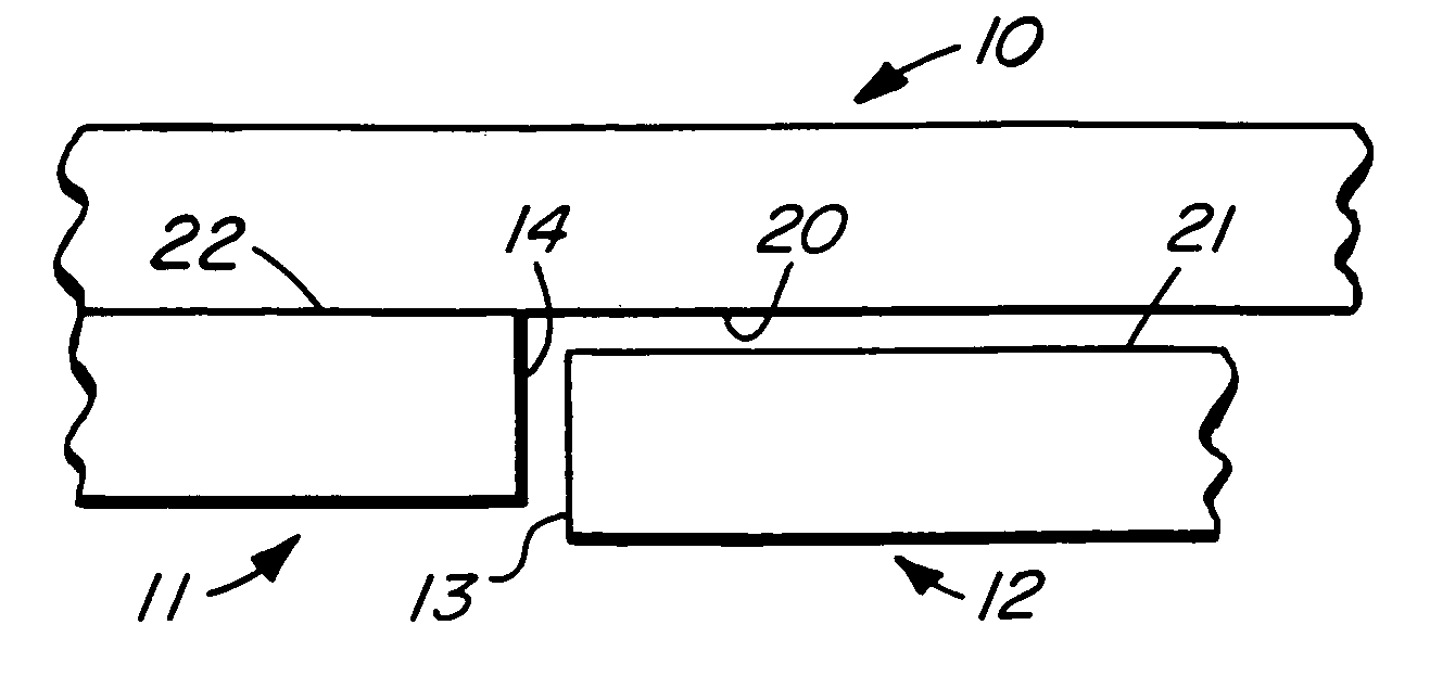
[0019] Referring now to the drawings, three(3) adjacent pieces of laminate flooring, namely first piece 10, second piece 11 and third piece 12 are illustrated in FIG. 1 which pieces are illustrated in their unassembled condition and which pieces 10, 11, 12 are intended to be joined together in an integral assembly on the top of a floor and which pieces illustrate the connection and the operation of the connection procedure according to the invention.

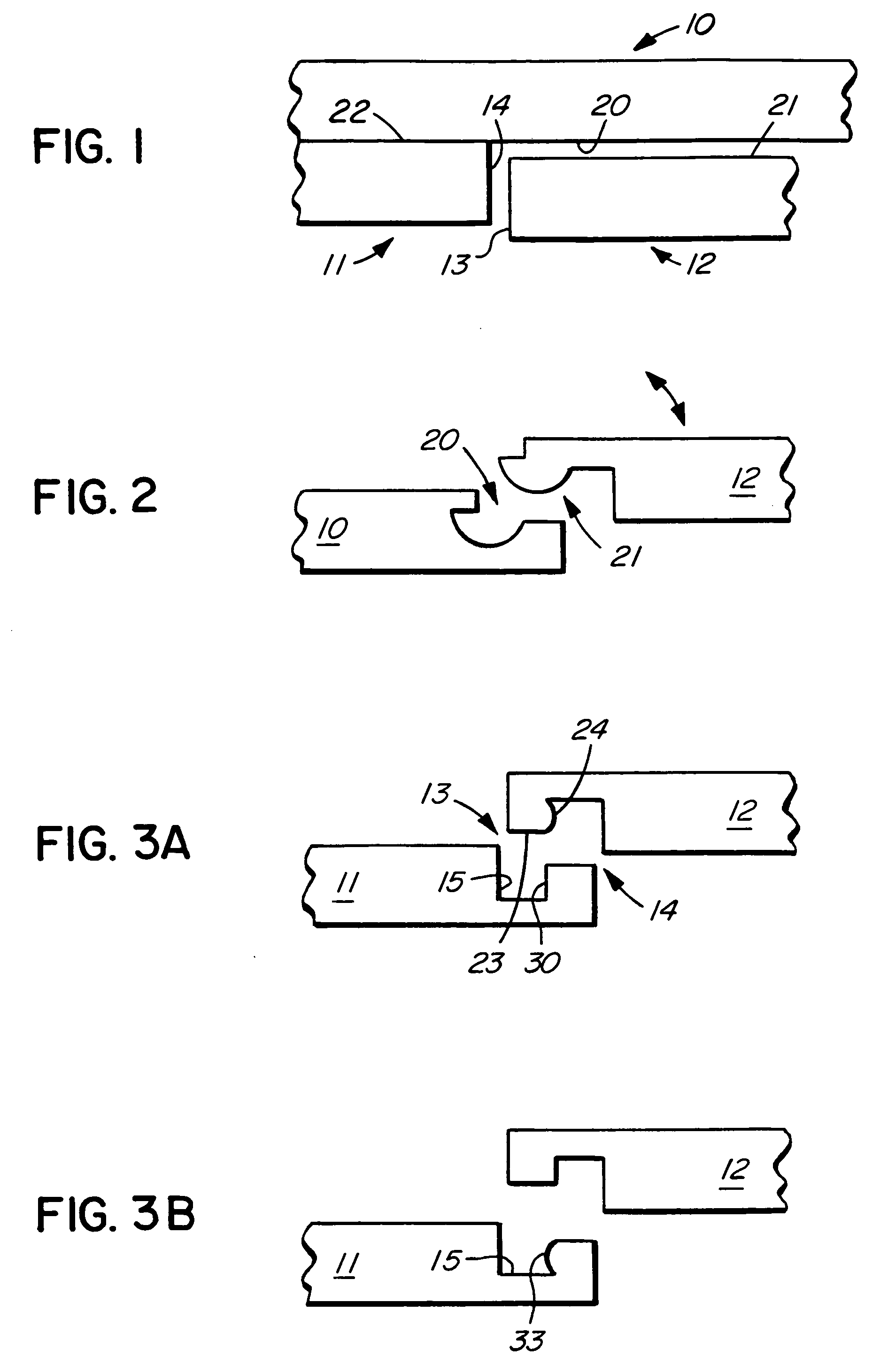
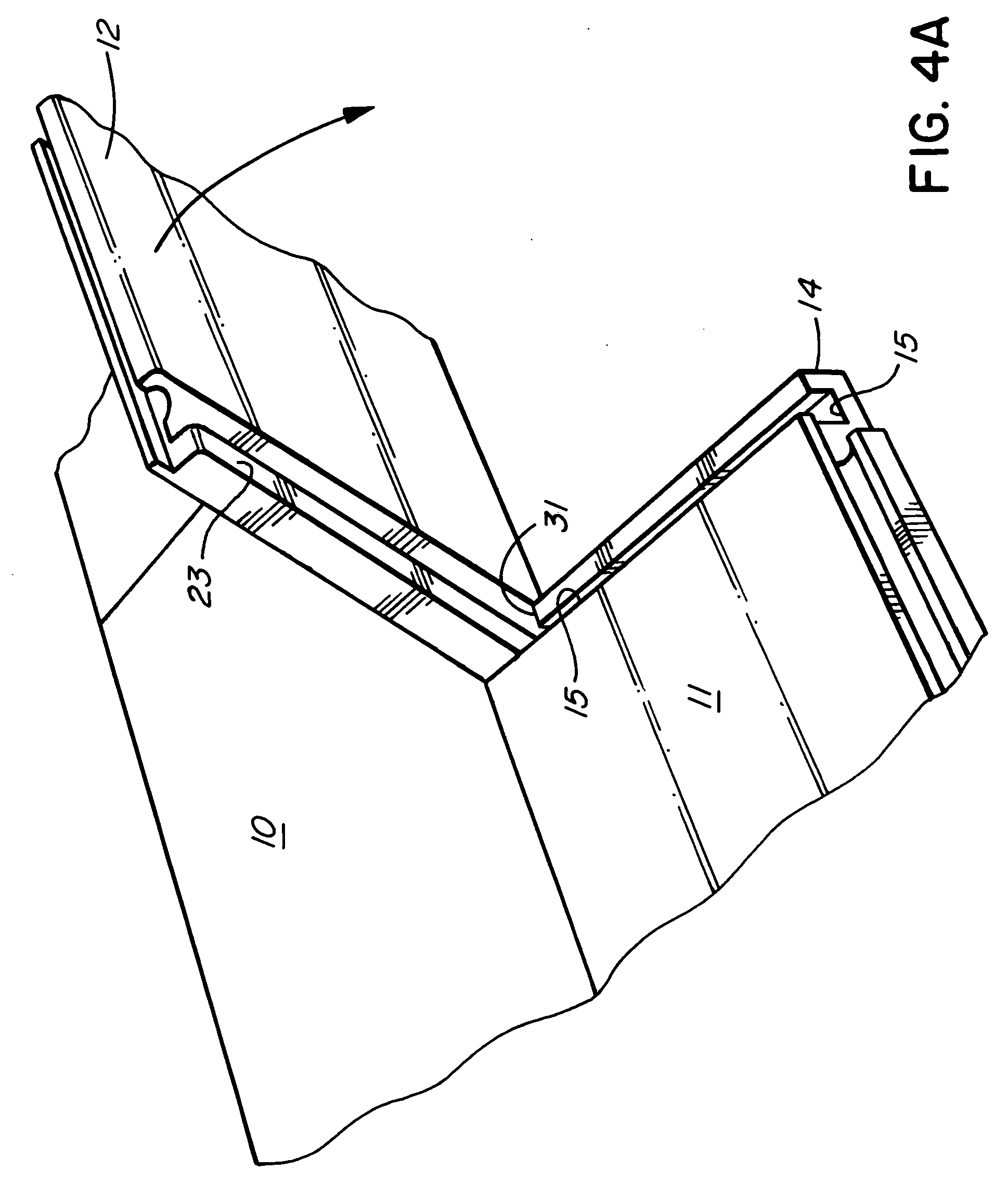
[0020] Each of the three pieces 10, 1112 have short and long edges, the short edges of first piece 10 not being illustrated for efficacy. Third piece 12 has a short edge 13 and second piece 11 has a short edge 14. First piece 10 has a long edge 20 which is intended to be connected to long edge 21 of third piece 12 and which long edge 20 is shown already connected to second piece 11 along long edge 22.

[0021] The connection area along the long edges 20, 21 of the first and third pieces 10, 12 are illustrated in greater detail in FIG. 2 w...


PUM


Abstract

A laminate panel with a beveled edge in the clear covering over the decorative layer. The bevel in the clear covering is produced by heating a roller and bringing it into operable contact with the clear covering adjacent the edge of the laminate panel. The heated roller melts the clear covering and produces the bevel as the laminate panel is moved past the roller while the roller rotates about its axis.

Description

CROSS-REFERENCE TO RELATED APPLICATION [0001] This application is a continuation-in-part of application Ser. No. 11 / 136,326 entitled IMPROVED CONNECTION FOR LAMINATE FLOORING, filed May 23, 2005 and co-pending herewith.INTRODUCTION [0002] This invention relates to a method for manufacturing beveled edges for use on laminate flooring and, more particularly, to a method of using heat treatment applied to a clear top layer covering the decorative top layer of such laminate flooring. BACKGROUND OF THE INVENTION [0003] With the introduction of laminate floor tiles which can be installed relatively easily by a non-commercial user, a number of patents have been obtained for the various techniques used in joining adjacent pieces of the tiles and which patents cover, generally, different tongue and groove attachment techniques. In joining such adjacent pieces of tiles, it is preferred to form a small beveled edge in the top surface of each of the adjoining tiles along the joining edges. The ...

Claims


Application Information

Patent Timeline
Patent Type & Authority Applications(United States)
IPC IPC(8): E04B2/00
CPCB24B9/18E04F15/02E04F2201/0153E04F2201/0138E04F15/02033
Inventor BRICE, JOHN NIGEL
Owner QUALITY CRAFT
Why Eureka
Try Eureka