Hose for installing loose fill insulation
a technology for installing loose fill insulation and hoses, which is applied in the direction of flexible pipes, spraying apparatus, mechanical apparatus, etc., can solve the problems of not having the manufacturer's specified density for the installed thermal resistance desired, and the condition of the insulation dispensing apparatus is not enough to fully “open up” the insulation
- Summary
- Abstract
- Description
- Claims
- Application Information
AI Technical Summary
Benefits of technology
Problems solved by technology
Method used
Image
Examples
first embodiment
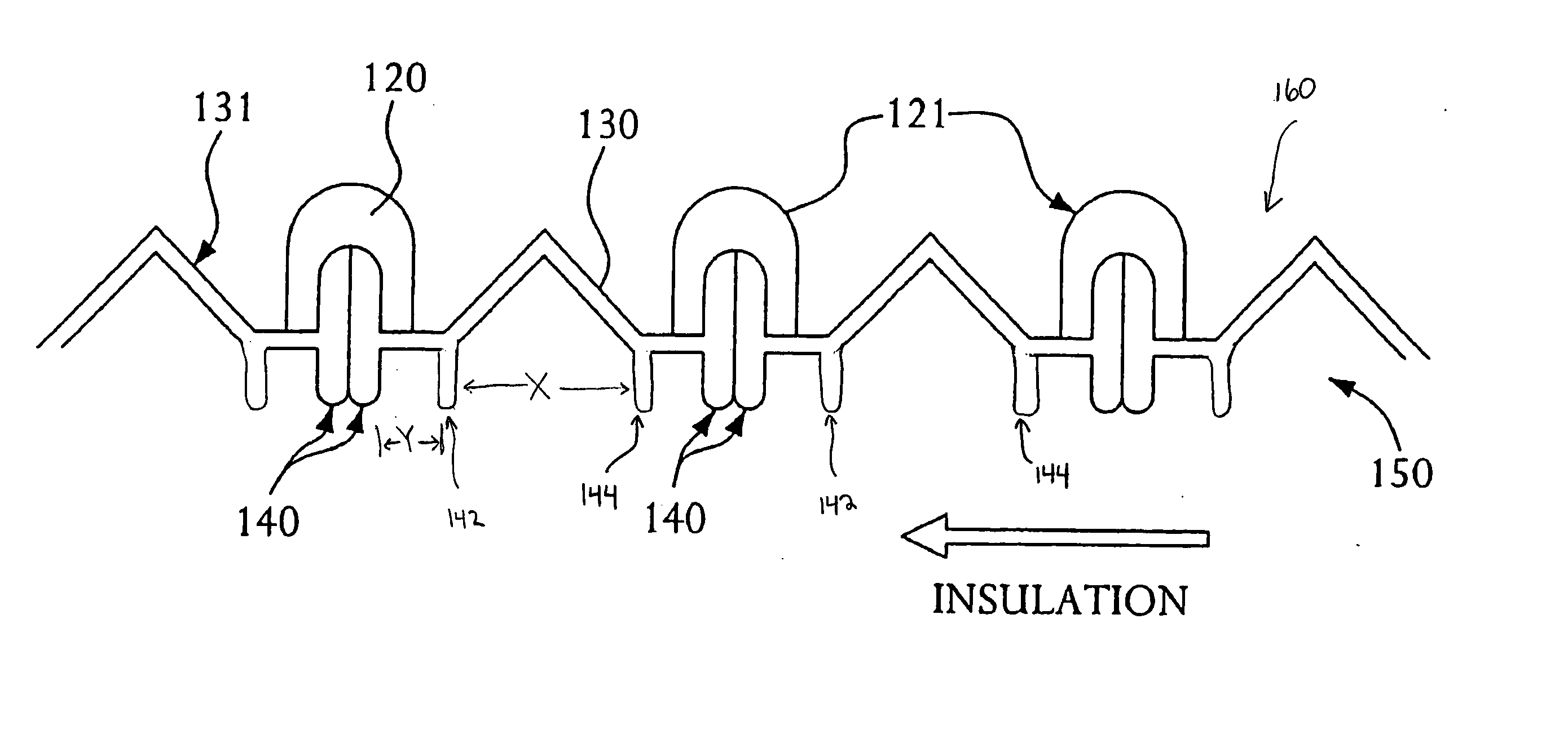
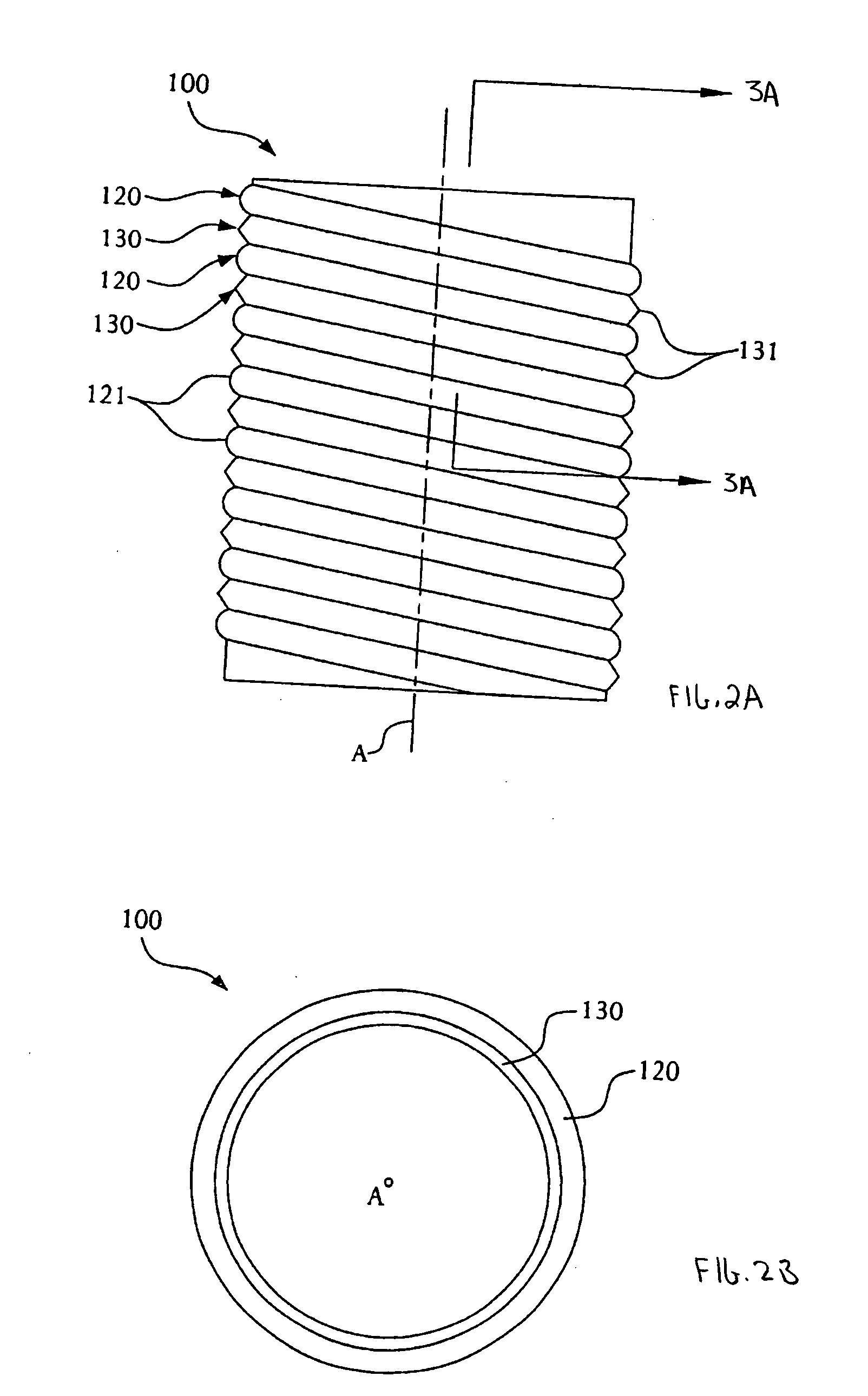
[0022]FIG. 3A shows a cross-sectional view of the tube100 taken along section line 3A-3A in FIG. 2A. FIG. 3A shows the plurality of helical projections. Reference numeral 150 indicates the inner portion of the tube 100 generally, and reference numeral 160 indicates an outer portion. Insulation (indicated by the arrow labeled “INSULATION”) passes along inner portion 150 from the direction of insulation inlet and it is dispensed through the tube 100 from an insulation output. In this embodiment, the helical projections 140 of inner web 130 extend into the inner portion 150 of the tube 100 by a specific length, typically 1 / 1000 of an inch (0.025 millimeters) to ¼ of an inch (6.35 millimeters), depending on the length of the insulation fiber and the diameter of the tube 100. They generally have a cross-sectional thickness of about 0.25 to 050 mm. The helical projections 140 substantially abut one another to collectively form a first helical projection (also referred to herein as “helica...
third embodiment
[0025] Although FIGS. 3A and 3B show the helical projections 140, 142, 144, 146, 148 as being substantially perpendicular to the axis A of the tube 100 (shown in FIG. 2A), other embodiments are also contemplated by the inventors. FIG. 3C shows a third embodiment where one or more helical projections (in this embodiment, the first and second spaced helical projections, now labeled 151, 152) are angled with respect to the axis A of the tube 100 by an angle less than ninety (90) degrees, and preferably at an angle between about 30-60°. A first exemplary projection 152 is angled so that it points towards the insulation input, i.e., the direction from which insulation flows through the tube in FIG. 3C. A second exemplary projection 151 is angled in the opposite direction, i.e., towards the output of the tube 100. The tips of these projections, i.e., the portions closest to longitudinal axis A, are spaced from each other, in an exemplary embodiment, a distance between about 0.25 inch, of ...
fourth embodiment
[0027] The helical projections need not project toward the longitudinal axis A for the same distance. FIG. 3D shows a fourth embodiment where the helical projections, now labeled 140′ and 140″, extend for different lengths. As also shown in FIG. 3D, adjacent turns of the tape that forms the tube 100 can be separated by a spacing element 170 disposed between the end portions of the tape. In one embodiment, spacing element 170 comprises and adhesive layer. In another exemplary embodiment, spacing element 170 comprises a portion of extruded cap 120 disposed between the end portions of the tape. In any event, the spacing created by spacing element 170 is preferably between about 0.5 to 3 mm.
[0028]FIG. 4 is a cross sectional view of the tube 100 showing how the inner web 130 (with helical projections 140, 142, 144) and outer cap 120 are formed. FIG. 4 shows an inner web 130 having a helical projection 140, 142, 144 as shown in FIG. 3A, but the foregoing explanation applies equally as wel...
PUM
 Abstract
Description
Claims
Application Information
 - R&D
- Intellectual Property
- Life Sciences
- Materials
- Tech Scout
- Unparalleled Data Quality
- Higher Quality Content
- 60% Fewer Hallucinations
Browse by: Latest US Patents, China's latest patents, Technical Efficacy Thesaurus, Application Domain, Technology Topic, Popular Technical Reports.
© 2025 PatSnap. All rights reserved.Legal|Privacy policy|Modern Slavery Act Transparency Statement|Sitemap|About US| Contact US: help@patsnap.com


