Rotation Sensing

a technology of rotation sensing and rotation, applied in the field of rotation sensing, can solve the problem that permanent magnets can occupy a significant volum

Inactive Publication Date: 2006-12-14
EQUIPMAKE
View PDF10 Cites 97 Cited by
  • Summary
  • Abstract
  • Description
  • Claims
  • Application Information

AI Technical Summary

Benefits of technology

[0009] The present invention further provides apparatus including a component as defined above and a sensor for detecting the magnetised regions of the component. Preferably, the sensor is a Hall effect sensor. The apparatus may include processing means coupled to the output of the sensor. In addition, the apparatus may include a plurality of sensors coupled to the processing means which are arranged to detect respective groups of magnetised regions on the component and / or on two or more rotatable components.

Problems solved by technology

However, the permanent magnet can occupy a significant volume.

Method used


Image

  • Rotation Sensing
  • Rotation Sensing
  • Rotation Sensing

Examples


Embodiment Construction

[0018] It should be noted that the Figures are diagrammatic and not drawn to scale. The same reference signs are generally to refer to corresponding or similar features in modified and different embodiments.

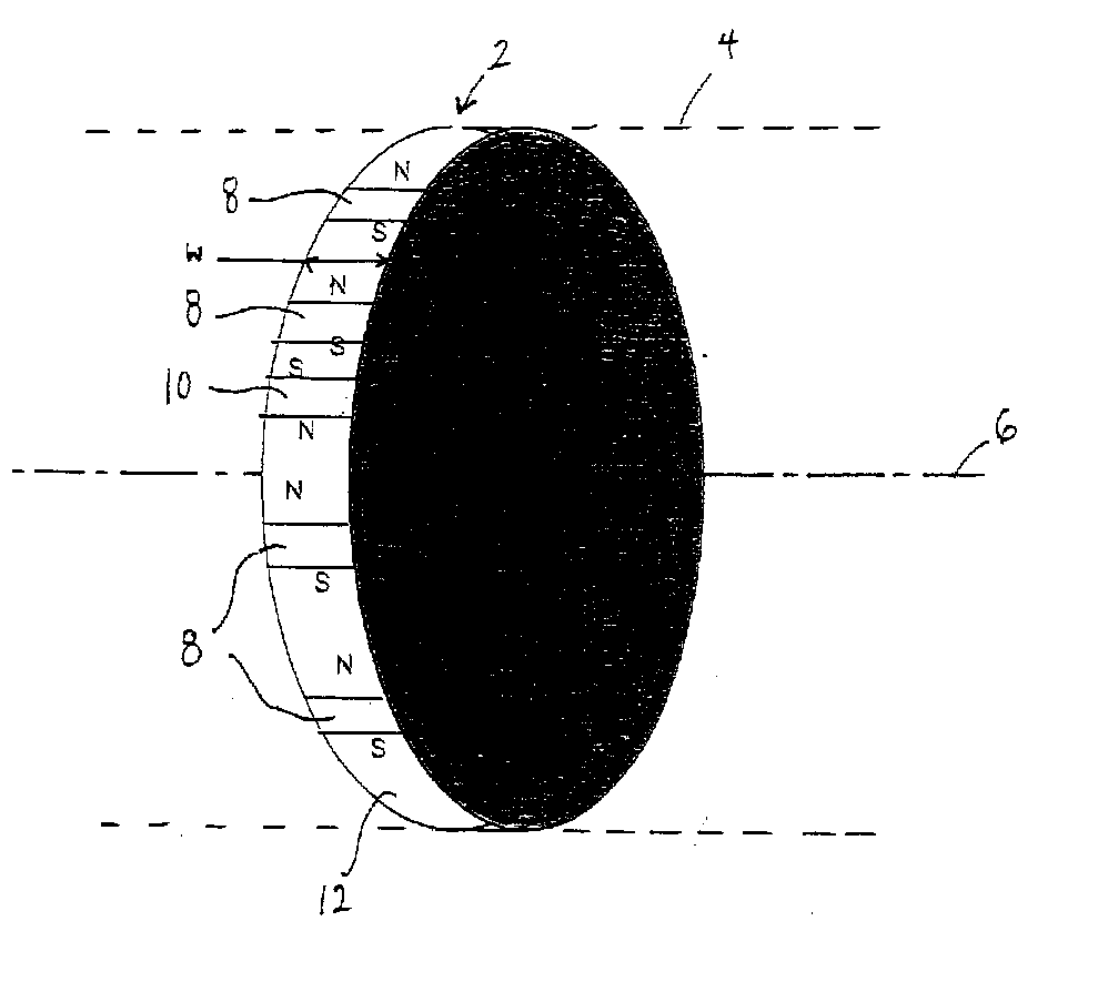
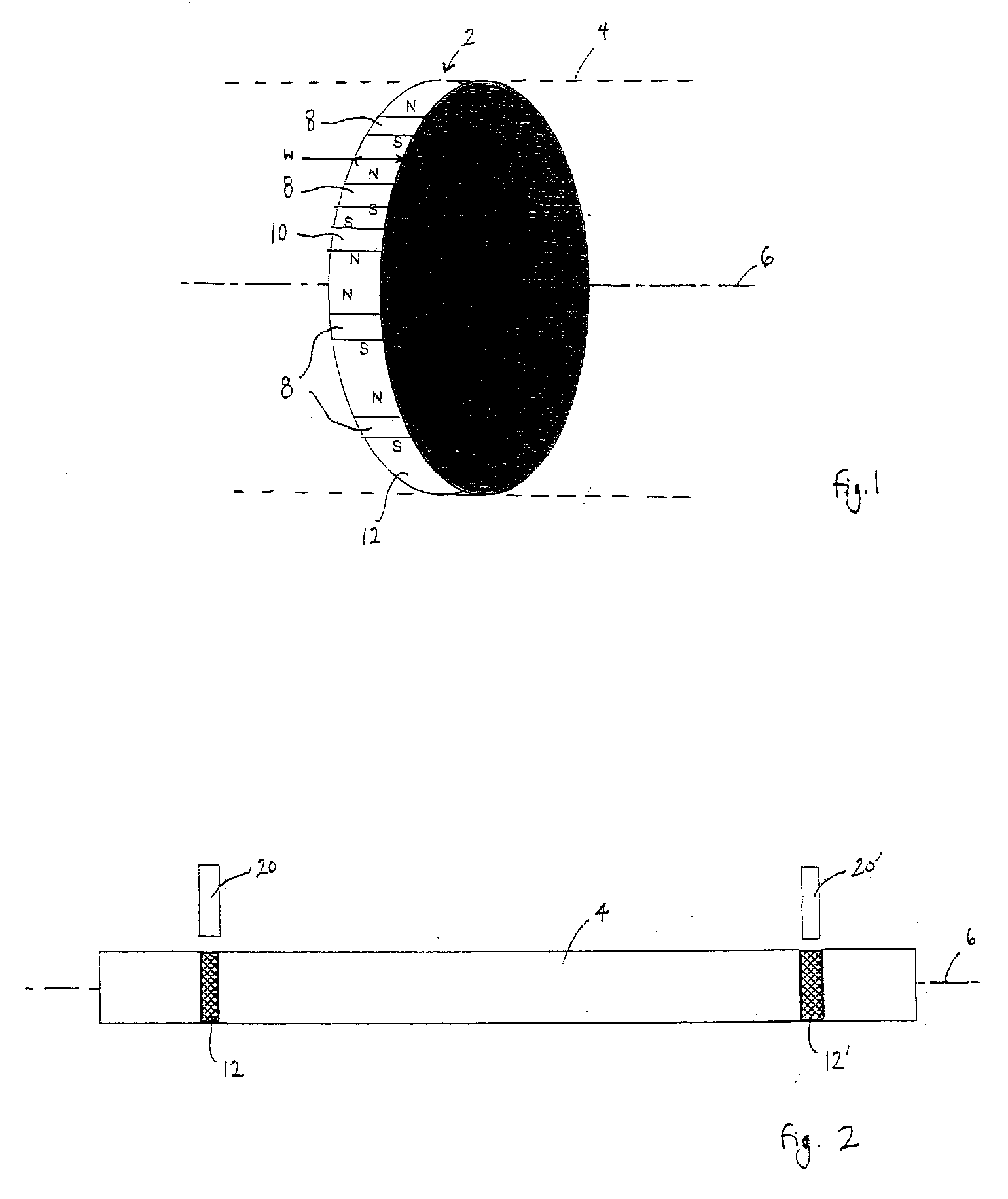
[0019]FIG. 1 shows a transverse slice 2 taken from a component in the form of a shaft 4. The shaft has an axis of rotation 6. A plurality of discrete magnetised regions 8 are provided at the surface of the shaft around the circumference of the slice 2. Regions 8 are equally spaced and magnetised in the same circumferential direction. A further discrete magnetised region 10 is provided between two other regions 8, and is magnetised in the opposite circumferential direction to the regions 8. Region 10 acts as a “sync” region.

[0020] The magnetised regions are formed in a strip of magnetisable material 12 which extends completely around the circumference of the shaft. The width, w, of the strip 12 measured in the axial direction may be approximately 10 mm, for example. The strip of...


PUM


Abstract

A compact arrangement which enables rotation of a component (4) of an apparatus to be sensed is provided. A component adapted for use in such an arrangement comprises a body having an axis of rotation (6) and a plurality of discrete magnetised regions (8) thereon, each formed in a layer of material (12) on the surface of the body, the magnetised regions being circumferentially distributed at substantially the same axial position to enable rotation of the component relative to a sensor (20, 20′) to be monitored. Methods for manufacturing a suitable component are also described. The arrangement disclosed enables the rotational position of component, such as a shaft for example, to be sensed using a Hall effect sensor, and a component may be modified in accordance with the invention without substantially increasing its volume.

Description

FIELD OF THE INVENTION [0001] The present invention relates to sensing the rotation of a component of an apparatus, and more particularly, a compact arrangement that enables the rotation of a component to be sensed. BACKGROUND OF THE INVENTION [0002] It is known to facilitate detection of the angular position of a rotor by fastening a permanent magnet to one end of the rotor shaft in close proximity to a Hall effect sensor. Such an arrangement allows angular position to be sensed in a contactless manner so that the sensor does not introduce frictional losses. However, the permanent magnet can occupy a significant volume. SUMMARY OF THE INVENTION [0003] The present invention provides a component comprising a body having an axis of rotation, and a plurality of discrete magnetised regions at the surface of the body which are circumferentially distributed at substantially the same axial position. [0004] Such a configuration enables the rotational position of component, such as a shaft f...

Claims


Application Information

Patent Timeline
Patent Type & Authority Applications(United States)
IPC IPC(8): G01B7/30G01D5/14G01P3/487
CPCG01D5/145G01L3/104G01P3/487G01D5/244
Inventor FOLEY, IAN DAVID
Owner EQUIPMAKE
Why Eureka
Try Eureka