Pump unit for magnetically driving an article

Inactive Publication Date: 2006-12-21
LIU MING HWA +2
View PDF4 Cites 7 Cited by
  • Summary
  • Abstract
  • Description
  • Claims
  • Application Information

AI Technical Summary

Problems solved by technology

The conventional pumping device is equipped with the motor so that the much room is occupied and the cost is relatively high.
This leads to high cost and inconvenience in use.

Method used


Image

  • Pump unit for magnetically driving an article
  • Pump unit for magnetically driving an article
  • Pump unit for magnetically driving an article

Examples


Embodiment Construction

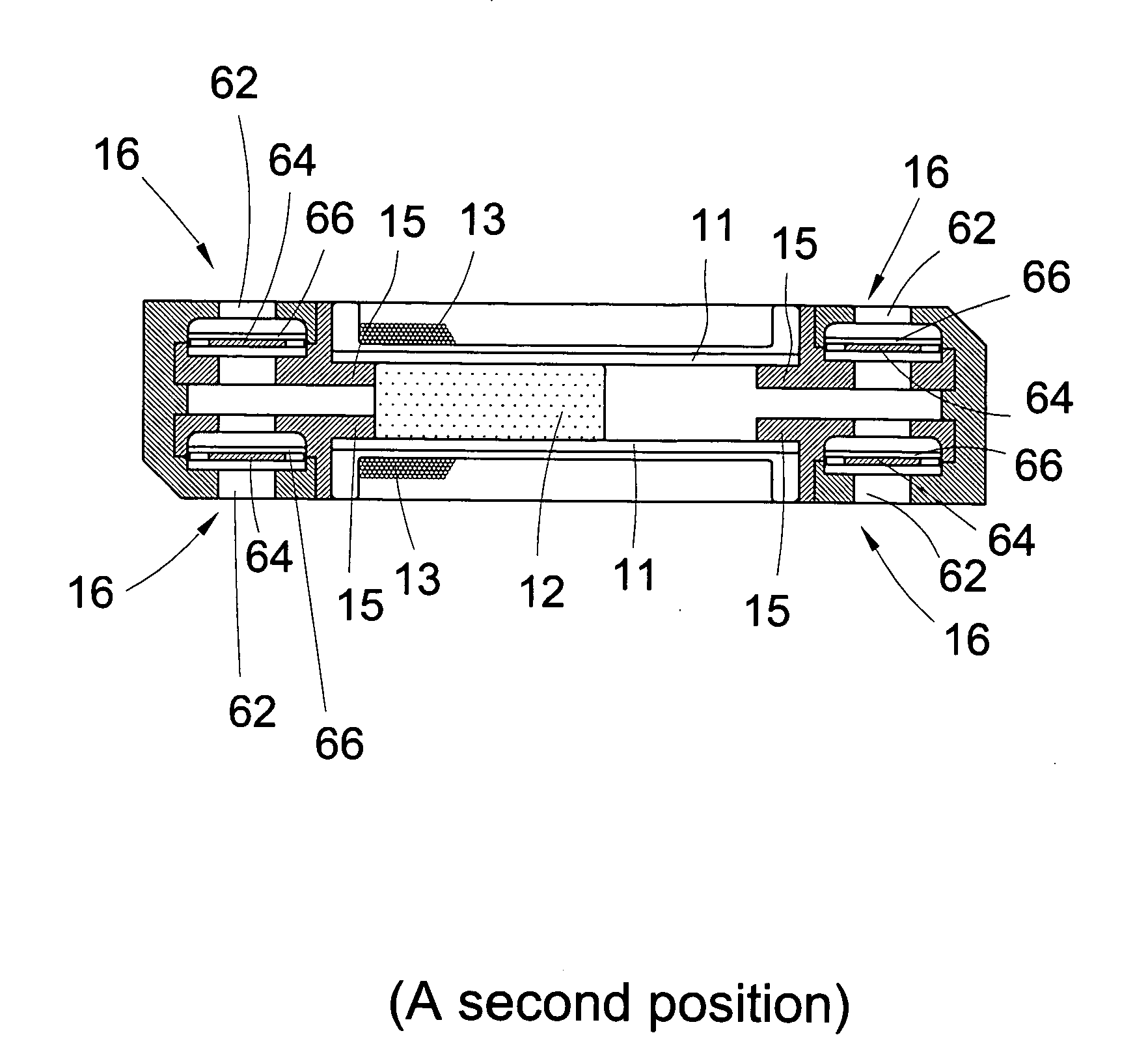
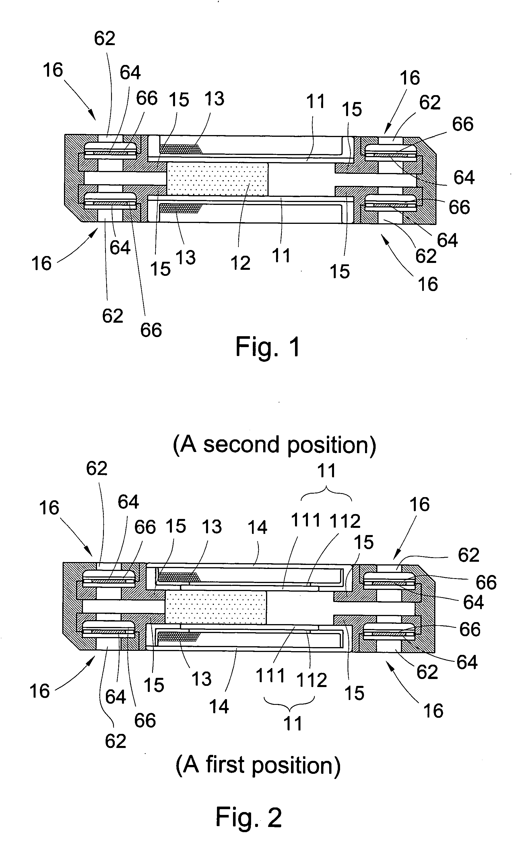
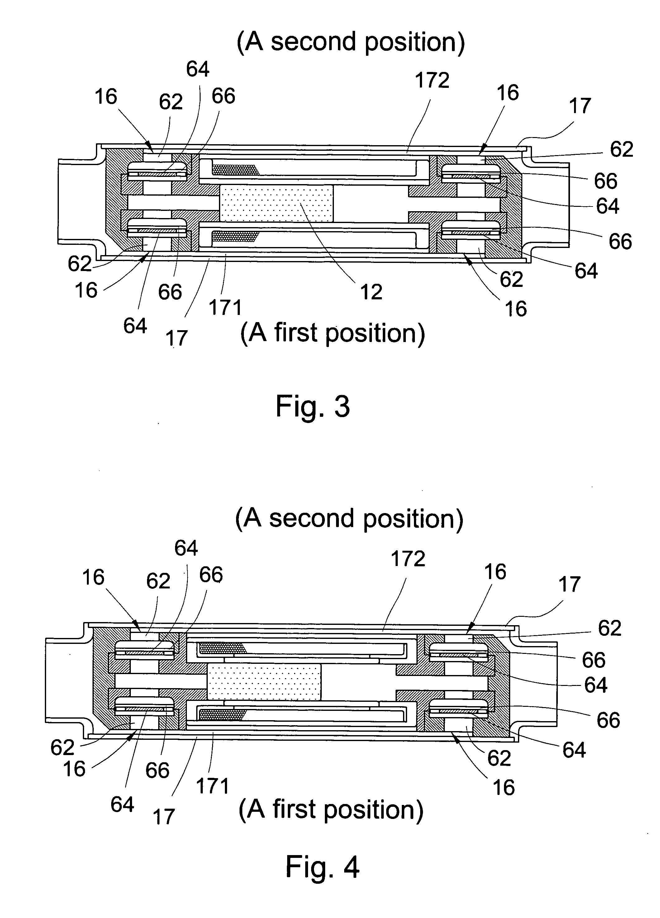
[0015] Please refer to FIG. 1. The pump unit for magnetically driving an article of the present invention includes a main body 11, an article 12 and a coil 13.

[0016] The main body 11 can be a tubular body having a certain length and an internal chamber.

[0017] The article 12 has a certain length and a configuration corresponding to the shape of the chamber. The article 12 is reciprocally movably positioned in the chamber. The article 12 can be a magnet or a superconductor subject to the action of magnetic force.

[0018] The coil 13 is wound around the main body 11 and connected with a circuit. The circuit provides a current such as an alternate current or a periodically alternate current for the coil 13 so as to drive the article 12 to move or reciprocally move for pushing a fluid on one side or two sides of the article 12.

[0019] In addition, at least an outer circumference of the main body is disposed with or formed of a magnetically conductive material such as silicon steel, iron...


PUM


Abstract

A pump unit for magnetically driving an article, including a main body, an article and a coil. The main body has an internal chamber. The article has a certain length and a configuration corresponding to a shape of the chamber. The article is reciprocally movably positioned in the chamber. The coil is wound around the main body and connected with a circuit. The circuit provides a current for the coil so as to drive the article to reciprocally move. The chamber of the main body communicates with two open ends of the main body. The pump unit further includes a first pair of one-way valve sections and a second pair of one-way valve sections. The first and second pairs of one-way valve sections are respectively disposed at two ends of the main body. When the article is reciprocally moved, a fluid can be only driven by the article to flow from a first position to a second position.

Description

BACKGROUND OF THE INVENTION [0001] The present invention is related to a device for driving a fluid, and more particularly to a pump unit for magnetically driving an article. [0002] The conventional pumping device is used to push a fluid to flow in a pipeline. The pumping device generally includes a water wheel apparatus or a pump unit communicating with a pipeline and externally connected with a motor. The motor operates to drive the water wheel to rotate or drive the pump unit to reciprocally move for pushing the fluid. Therefore, the fluid can be circulated in the pipeline or transferred from one place to another place. [0003] The conventional pumping device is equipped with the motor so that the much room is occupied and the cost is relatively high. Also, one single pipeline system is often equipped with one single pump. Alternatively, one single pumping device can be used in cooperation with two pipeline systems. In this case, many switch valves or check valves must be mounted ...

Claims


Application Information

Patent Timeline
IPC IPC(8): F04B17/04
CPCF04B17/044F04B35/045F04B53/10F04B53/16F05B2210/11F05B2210/12Y10S417/00
Inventor LIU, MING-HWACHEN, BRIAN D. F.CHIEN, CHIN-PANG
Owner LIU MING HWA
Why Eureka
Try Eureka