Thermoelectric converter for a heat transfer device

a heat transfer device and thermoelectric converter technology, applied in the direction of generators/motors, lighting and heating apparatus, heating types, etc., can solve the problems of insufficient connection strength of lead wires, thermoelectric elements may malfunction, and the effect of adding undesirable cost and time to the manufacturing process

Inactive Publication Date: 2006-12-28
DENSO CORP
View PDF4 Cites 29 Cited by
  • Summary
  • Abstract
  • Description
  • Claims
  • Application Information

AI Technical Summary

Problems solved by technology

The soldering may add undesirable cost and time to the manufacturing process.
Also, the connection str...

Method used


Image

  • Thermoelectric converter for a heat transfer device
  • Thermoelectric converter for a heat transfer device
  • Thermoelectric converter for a heat transfer device

Examples


first embodiment

(First embodiment)

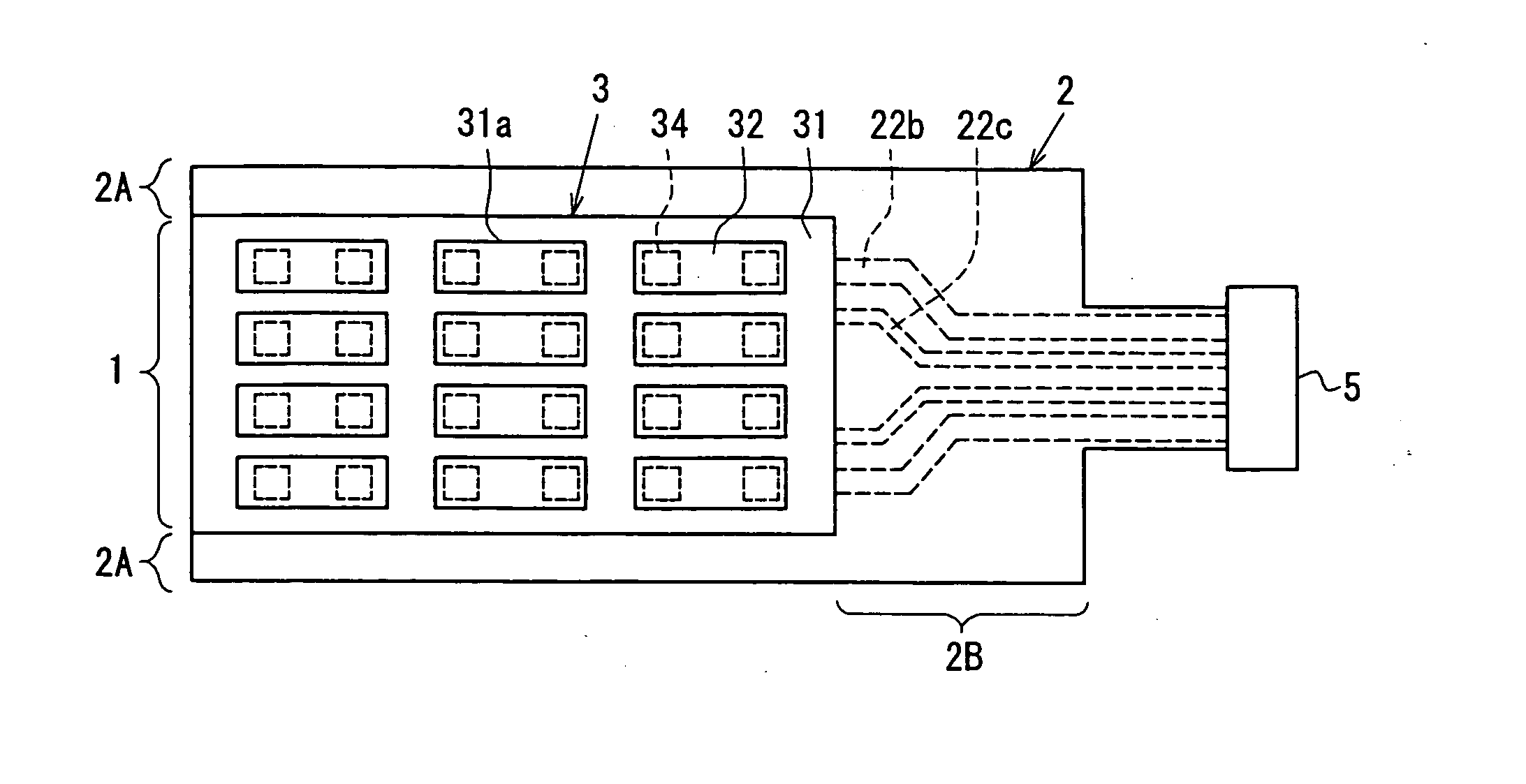
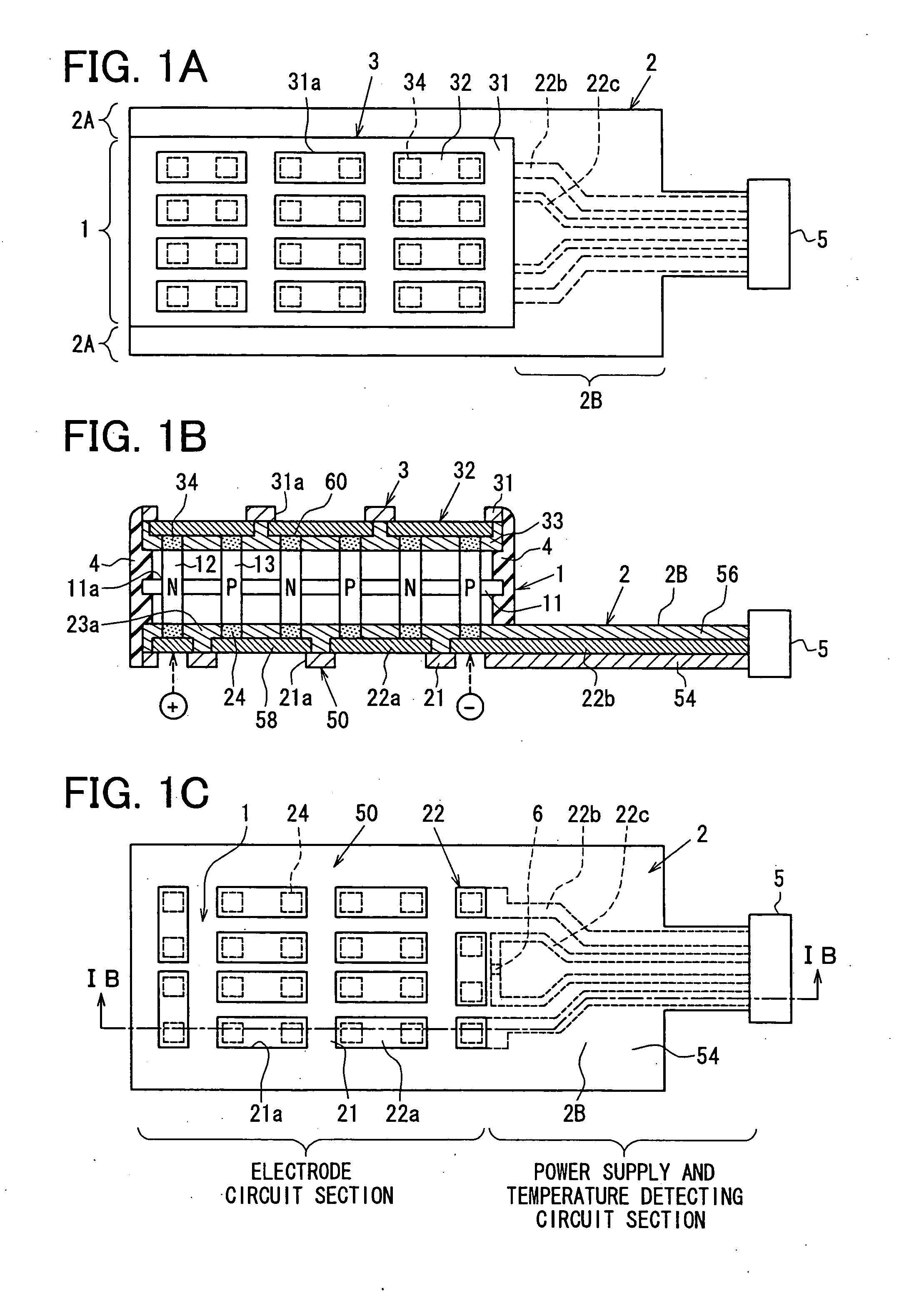
[0019] Referring initially to FIGS. 1A-1C, one embodiment of a thermoelectric converter is shown. The thermoelectric converter generally includes a thermoelectric element assembly body 1, and an extension member 2.

[0020] The thermoelectric element assembly body 1 includes a plurality of dissimilar thermoelectric elements 12, 13 arranged in an array. In one embodiment, the thermoelectric elements 12, 13 are P-type thermoelectric elements 13 and N-type thermoelectric elements 12. In the embodiment shown, the array includes four rows and six columns of thermoelectric elements 12, 13. The thermoelectric elements 12, 13 are alternately positioned.

[0021] Also, the thermoelectric elements 12, 13 extend through corresponding apertures 11a of a holding member 11. In the embodiment shown, the holding member 11 is flat and plate shaped. The holding member 11 is made of an insulating material such as glass epoxy, PPS resin, LCP resin or PET resin, etc.

[0022] The thermoelect...


PUM


Abstract

A thermoelectric converter is disclosed which includes a body and an extension member. The body includes a plurality of dissimilar thermoelectric elements in an array. The body also includes a first substrate with a first electrically conductive pattern portion that is electrically connected to the plurality of dissimilar thermoelectric elements. Also, the body includes a second substrate with a second electrically conductive pattern portion that is electrically connected to the plurality of dissimilar thermoelectric elements. The extension member includes an extension pattern portion that is electrically connected to at least one of the first and second electrically conductive pattern portions. The extension member extends away from the body.

Description

CROSS REFERENCE TO RELATED APPLICATIONS [0001] The following is based on and claims priority to Japanese Patent Application No. 2005-185487, filed Jun. 24, 2005, and Japanese Patent Application No. 2005-370103, filed Dec. 22, 2005, the disclosures of which are incorporated herein by reference. FIELD [0002] The present invention relates to a thermoelectric converter and, more particularly, to a thermoelectric converter for a heat transfer device. BACKGROUND [0003] Theremoelectric devices have been proposed, which rely on the Peltier effect (see, e.g., Japanese Patent No. 2002-208741). In one example, a thermoelectric converter has P-type thermoelectric elements and N-type thermoelectric elements alternately and adjacently fitted to plural opening portions formed in an insulating plate. The device also has an electrode section for sequentially connecting the P-type thermoelectric elements and the N-type thermoelectric elements so as to sequentially supply an electric current to the ad...

Claims


Application Information

Patent Timeline
IPC IPC(8): H01L35/28F24F1/00H01L35/10H01L35/32H02N11/00
CPCH01L35/32H01L35/10H10N10/82H10N10/17
Inventor NIIMI, YASUHIKOITO, YUJIKUROYANAGI, ISAO
Owner DENSO CORP
Why Eureka
Try Eureka