Golf ball marking system

Inactive Publication Date: 2006-12-28
PELZ DAVID
View PDF16 Cites 40 Cited by
  • Summary
  • Abstract
  • Description
  • Claims
  • Application Information

AI Technical Summary

Benefits of technology

[0005] The object of this invention is to provide an improved marking system for golf balls whereby the golfer can determine immediately whether or not the

Problems solved by technology

Golfers continuously struggle to improve the quality of their putting.
Small errors in alignment between 1) the face of the putter and ball at impact, 2) the direction of motion of the putter relative to the proper start

Method used


Image

  • Golf ball marking system
  • Golf ball marking system
  • Golf ball marking system

Examples


Embodiment Construction

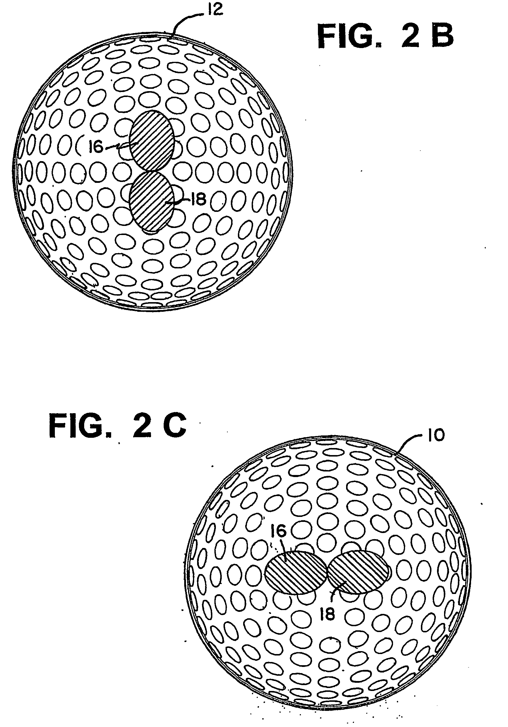
[0016] In the specification and claims, the terms “equator” and “polar regions” are used to define relative positions on a golf ball. The “equator” as its name implies, is the circumference of the ball at its midpoint, i.e., its largest diameter, or a great circle. The “polar regions” refer to the regions of the ball which lie on and around the intersection of the ball and an axis of the ball perpendicular to the plane in which the equator lies.

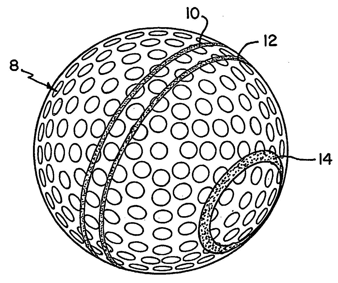
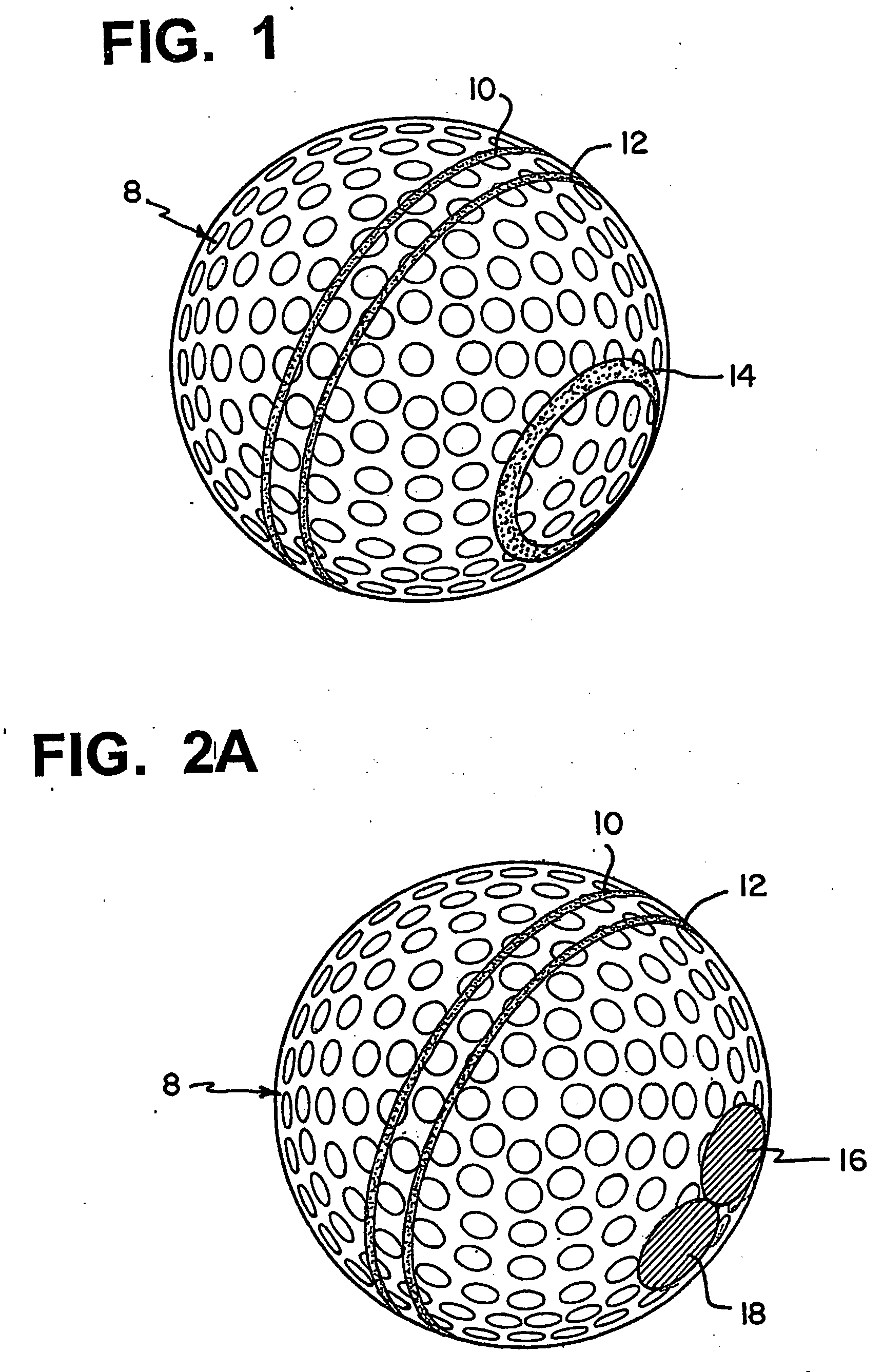
[0017] The principles of the invention are explained with respect to FIGS. 1 and 2 which illustrate a golf ball marked in accordance with two embodiments of the invention.

[0018] In FIG. 1 a golf ball 8 includes two closely spaced equatorial O-rings (circumferential stripes) 10 and 12 equally offset from an equator of the ball. In accordance with this embodiment of the invention, a marking in the shape of a circle or polar o-ring 14 is printed in each polar region of the golf ball (only one circle 14 is shown in FIG. 1). The polar o-rings 14...


PUM


Abstract

In accordance with the invention, a golf ball is marked with two equatorial O-rings adjacent an equator of the ball and equally spaced therefrom, which are in a golfer's full view of the top side of the ball when the ball is accurately aligned to its desired initial starting line and a golfer is properly positioned to putt. The polar regions of the ball are also imprinted with a pattern which is essentially invisible to the golfer when properly positioned to putt. When the ball is aligned to a particular starting direction, and properly struck precisely and squarely and rolls purely in that starting direction, the equatorial O-rings will roll without wobble, and the polar O-rings will remain essentially invisible to the golfer. But when side spin is imparted to the ball at impact, the equatorial O-rings (circumferential lines) will appear to wobble as the ball rolls, and the polar O-rings will become periodically visible and emphasize the appearance of wobble. The quantity of the polar region imprints which become visible and obvious, and which enhance the appearance of wobble as the ball is rolling, provides an indication of the extent to which side spin has been imparted to the ball by the putting stroke. This feedback to the golfer after every putt, as to the magnitude of the apparent wobble (i.e. amount of side spin) his or her stroke imparted at impact, allows the golfer to differentiate between good and poor putting strokes. Such learning will inevitably help the golfer improve his or her putting. A putter for use with the ball marked as described above includes a central region which simulates the appearance of a golf ball cover. Two lines are printed on this central region converging from the back of the putter toward the front surface with the lines adapted to be aligned with the equatorial O-rings on the ball. The regions of the upper surface of the putter contiguous to the central region may be printed or painted with a coating that simulates grass.

Description

[0001] This application claims priority pursuant to 35 U.S.C. §119 based on U.S. Provisional Application Ser. No. 60 / 421,749 filed Oct. 28, 2002, and U.S. Provisional Application Ser. No. 60 / 476,792 filed Jun. 6, 2003, the entire disclosures of which are hereby incorporated by reference.[0002] This invention relates to golf. More particularly, this invention relates to a system for marking golf balls and / or putters so as to help a golfer align putts in a particular direction, and then determine whether the ball was struck properly (initially rolled in that direction) when it was putted. BACKGROUND OF THE INVENTION [0003] Golfers continuously struggle to improve the quality of their putting. Innumerable putters have been designed over the years to improve putting accuracy. Many different training aids have also been designed with a view toward improving the putting stroke and / or the golfer's alignment. [0004] Accurate putting depends in the first place on the putter's skill in “readi...

Claims


Application Information

Patent Timeline
IPC IPC(8): A63B69/36A63BA63B45/02
CPCA63B37/14A63B43/008A63B37/0022A63B69/3685A63B69/3688A63B45/02
Inventor PELZ, DAVID
Owner PELZ DAVID
Why Eureka
Try Eureka