
Blade Tensioner

a blade shoe and tensioner technology, applied in the direction of belts/chains/gearings, mechanical instruments, belts/chains/gearings, etc., can solve the problems of complex assembly process and increased components, and achieve the effect of preventing the blade shoe from falling out of the pin

Inactive Publication Date: 2007-01-04
BORG WARNER MORSE TEC JAPAN KK
View PDF8 Cites 11 Cited by
  • Summary
  • Abstract
  • Description
  • Claims
  • Application Information

AI Technical Summary

Benefits of technology

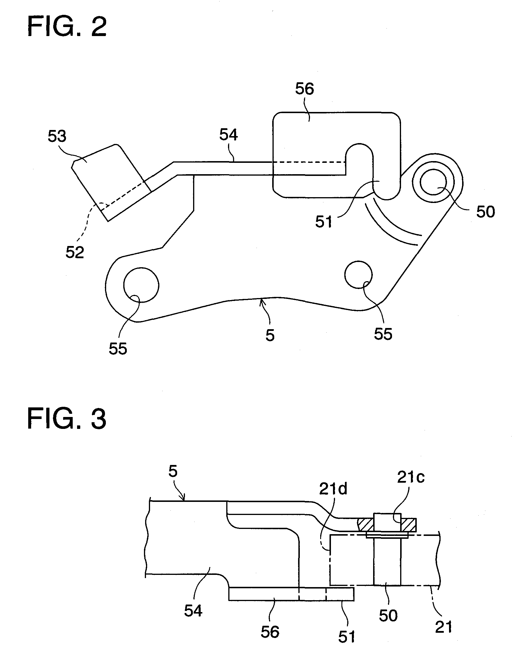
[0007] According to the first aspect of the present invention, since the bulge portion is provided at the proximal end portion of the blade shoe and the extended portion is provided at the bracket, which is disposed beside the bulge portion of the blade shoe, by simply fitting the proximal end portion of the blade shoe to the pin of the bracket, prevention of the blade shoe from falling out of the pin can be achieved. This eliminates the necessity for providing the pin with a washer in use for prevention of fall-off of the blade shoe and for caulking the tip of the pin. Thereby, the number of components can be reduced and the assembly process can be simplified. Also, in this case, during operation of the blade-type tensioner, the proximal end portion of the blade shoe is guided by the bracket on both sides thereof.
[0009] According to the second aspect of the present invention, since the extended portion is provided at the bracket, which is disposed beside the chain sliding surface of the blade shoe, by simply fitting the proximal end portion of the blade shoe to the pin of the bracket, prevention of the blade shoe from falling out of the pin can be achieved. This eliminates the necessity for providing the pin with a washer in use for prevention of fall-off of the blade shoe and for caulking the tip of the pin. Thereby, the number of components can be reduced and the assembly process can be simplified.
[0013] According to the method of the present invention, the blade shoe can be fitted to the bracket without interfering with the extended portion of the bracket, and thereafter the assemble man simply rotates the blade shoe around the pin to assemble the blade-type tensioner. In such a way, prevention of the blade shoe from falling out of the pin can be simply achieved.

Problems solved by technology

Therefore, in the prior-art blade-type tensioner, the components are increased in number and the assembly process is complicated.

Method used


Image

  • Blade Tensioner
  • Blade Tensioner
  • Blade Tensioner

Examples


first embodiment

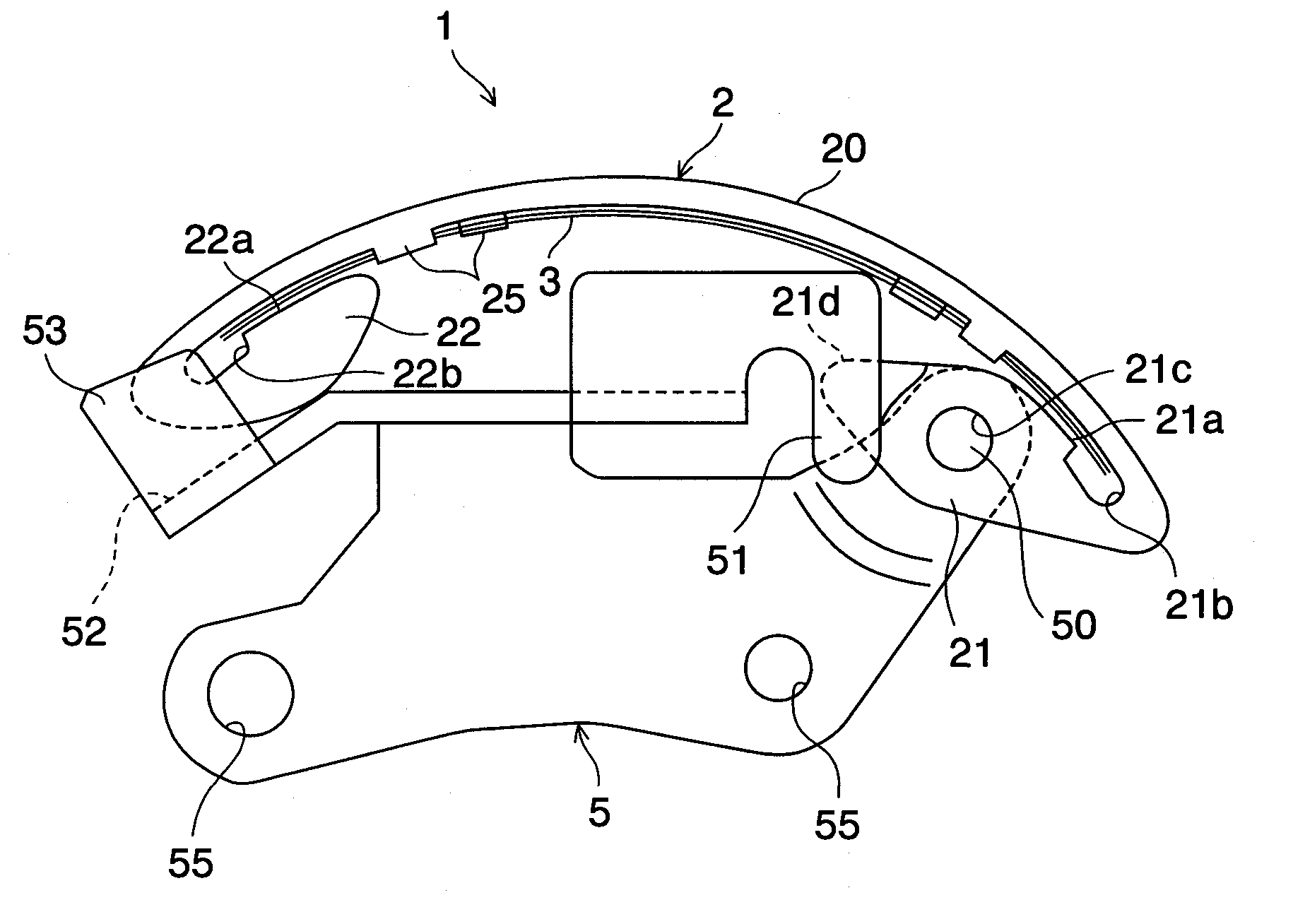
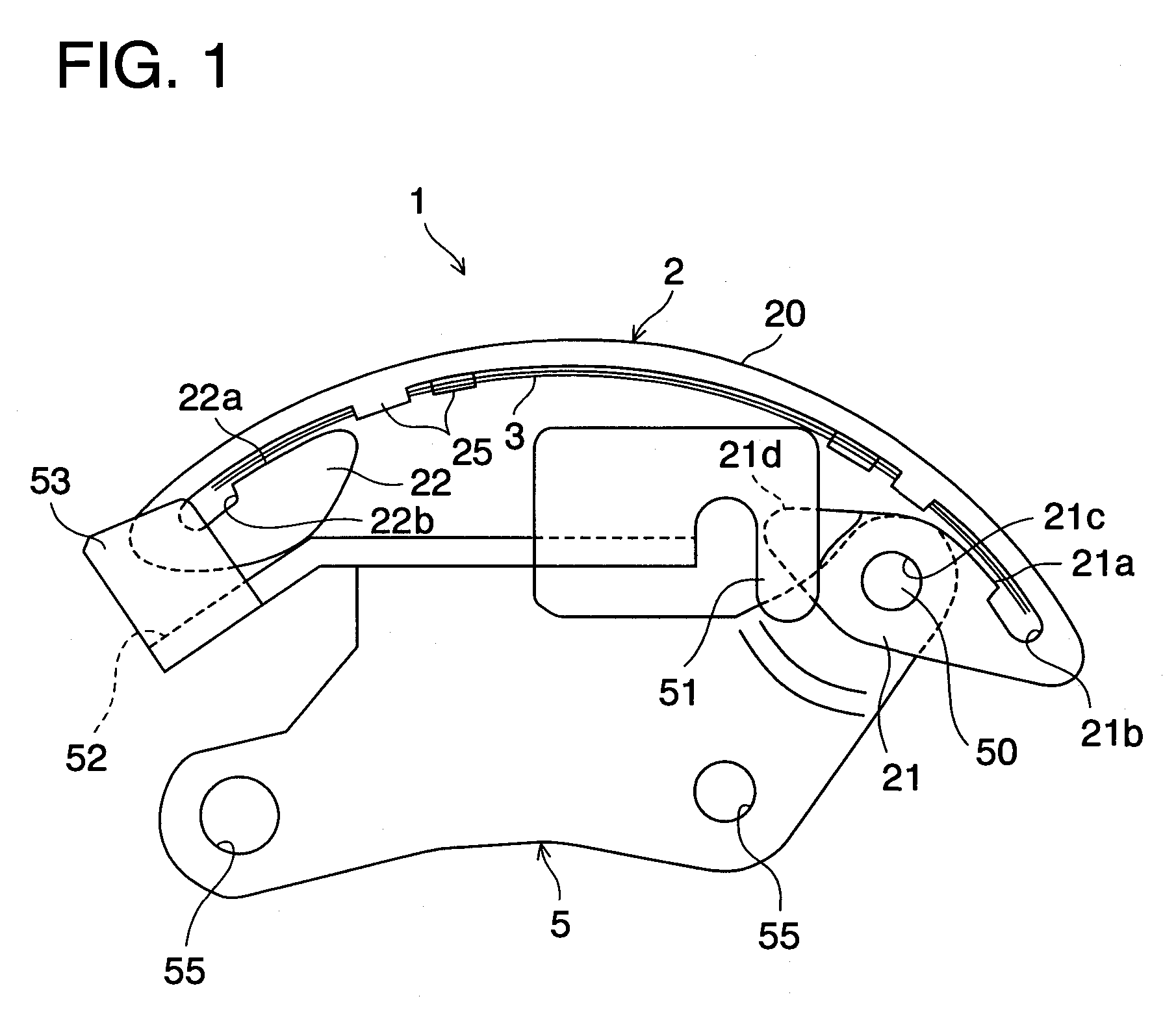
[0021]FIG. 1 shows a blade-type tensioner according to the present invention. As shown in FIG. 1, a blade-type tensioner (1) includes a blade shoe (2) having an arcuately curved chain sliding surface (20), a plurality of leaf-spring-shaped blade springs (3) provided and stacked on the opposite side of the chain sliding surface (20) of the blade shoe (2) to exert a spring force on a chain (not shown) via the blade shoe (2), and a bracket (5), preferably made of sheet metal, to rotatably support the proximal end portion (21) of the blade shoe (2) and slidably support the distal end portion (22) of the blade shoe (2).

[0022] The blade shoe (2) has an indentation (21a) formed in the proximal end portion (21) to receive an end of the blade spring (3). The indentation (21a) has a concave portion (21b) to avoid interference with the end of the blade spring (3). Similarly, the blade shoe (2) has an indentation (22a) formed in the distal end portion (22) to receive the other end of the blade ...

second embodiment

[0032] FIGS. 5 to 7 show a blade-type tensioner according to the present invention. In these drawings, like reference numbers indicate identical or functionally similar elements.

[0033] In the second embodiment, the extended portion provided at the bracket (5) is different in shape and position from that of the first embodiment. As shown in FIGS. 5 and 6, the base face (54) extending at the back of the slide face (52) of the bracket (5) has an upraised wall (58) provided at the rear end of the base face (54) and extending upwardly from a side edge portion of the base face (54). The upraised wall (58) is disposed beside the side surface (20a) of the chain sliding surface (20) of the blade shoe (2) and preferably extends over the chain sliding surface (20). The upraised wall (58) restricts the lateral movement of the blade shoe (2) caused by the travel of the proximal end portion (21) of the blade shoe (2) along the pin (50). In this case, the proximal end portion (21) of the blade sho...


PUM


Abstract

A blade-type tensioner 1 for imparting tension to a chain includes a blade shoe 2 with a chain sliding surface 20 that extends between the proximal end portion 21 and the distal end portion 22 of the blade shoe 2. The blade-type tensioner 1 further includes a blade spring 3 disposed opposite the chain sliding surface 20 of the blade shoe 2, and a bracket 5 that has a fixed pin 50 inserted into the pin aperture 21c of the proximal end portion 21 of the blade shoe 2 and that has a slide face 52 to slidably support the distal end portion 22 of the blade shoe 2. The proximal end portion 21 of the blade shoe 2 has a bulge portion 21d that bulges out toward the distal end portion 22 of the blade shoe 2. The bracket 5 has an extended portion 51 disposed at a position where the extended portion 51 overlaps with the bulge portion 21d of the proximal end portion 21 of the blade shoe 2 during operation of the blade-type tensioner 1 so as to restrict the lateral movement of the proximal end portion 21 of the blade shoe 2 along the pin 50.

Description

TECHNICAL FIELD [0001] The present invention relates to a blade-type tensioner that can decrease the number of components and simplify the assembly process. DESCRIPTION OF THE PRIOR ART [0002] Blade-type tensioners have been used to impart tension to chains such as timing chains or auxiliary drive chains for oil pumps in automotive engines. As shown in Japanese patent application laying-open publication No. 2000-234656, a blade-type tensioner of prior art is formed of a blade shoe having an arcuately curved chain sliding surface, a blade spring disposed opposite the chain sliding surface of the blade shoe, and a bracket that rotatably supports the proximal end portion of the blade shoe and that slidably supports the distal end portion of the blade shoe. [0003] During operation of the blade-type tensioner, a spring force in accordance with the deformation of the blade spring is exerted on the chain through the blade shoe and thereby tension in the chain is maintained. [0004] Typicall...

Claims


Application Information

Patent Timeline
Patent Type & Authority Applications(United States)
IPC IPC(8): F16H7/08F16H7/18
CPCF16H2007/0804F16H7/08
Inventor MISHIMA, KUNIHIKO
Owner BORG WARNER MORSE TEC JAPAN KK
Learn More