Suction mounted bar code symbol reading system, apparatus and stand

a reading system and bar code technology, applied in the direction of instruments, sensing record carriers, sensing by electromagnetic radiation, etc., can solve the problems of scanner damage, requiring modification of the countertop, irreversible damage to the countertop,

Inactive Publication Date: 2007-01-25
TALLEY HARRY +1
View PDF47 Cites 33 Cited by
  • Summary
  • Abstract
  • Description
  • Claims
  • Application Information

AI Technical Summary

Benefits of technology

[0009] Accordingly, a primary object of the present invention is to provide a novel optical bar code symbol reading system for mounting a bar code symbol reading device to a surface, which avoids the shortcomings and drawbacks of prior art systems.
[0010] Another object of the present invention is to provide a novel apparatus for mounting a bar code scanner to a flat surface without the use of hardware, which avoids the shortcomings and drawbacks of prior art apparatus.
[0011] Another object of the present invention is to provide a novel bar code scanning system, comprising a bar code scanner; and a suction-cup apparatus fastened to said bar code scanner, which avoids the shortcomings and drawbacks of prior art bar code scanning systems.
[0012] Another object of the present invention is to provide a novel stand that is rigidly connected to a mounting apparatus for mounting a bar code scanner to a flat surface without the use of hardware, which avoids the shortcomings and drawbacks of prior art stands.

Problems solved by technology

However, with reference to prior art stand devices of this type, because they are not rigidly connected to the POS countertop there is an increased likelihood that the stand device might get tipped over, possibly resulting in damage to the scanner.
However, the base must be permanently secured to the countertop, which requires modification to the countertop and irreversible damage to the countertop if the scanner system was ever removed due to an equipment upgrade or a change in operational requirements.
Unfortunately, the mounting of the base to the countertop requires modification to the countertop and irreversible damage to the countertop if the scanner system was ever removed due to an equipment upgrade or a change in operational requirements.

Method used


Image

  • Suction mounted bar code symbol reading system, apparatus and stand
  • Suction mounted bar code symbol reading system, apparatus and stand
  • Suction mounted bar code symbol reading system, apparatus and stand

Examples


Embodiment Construction

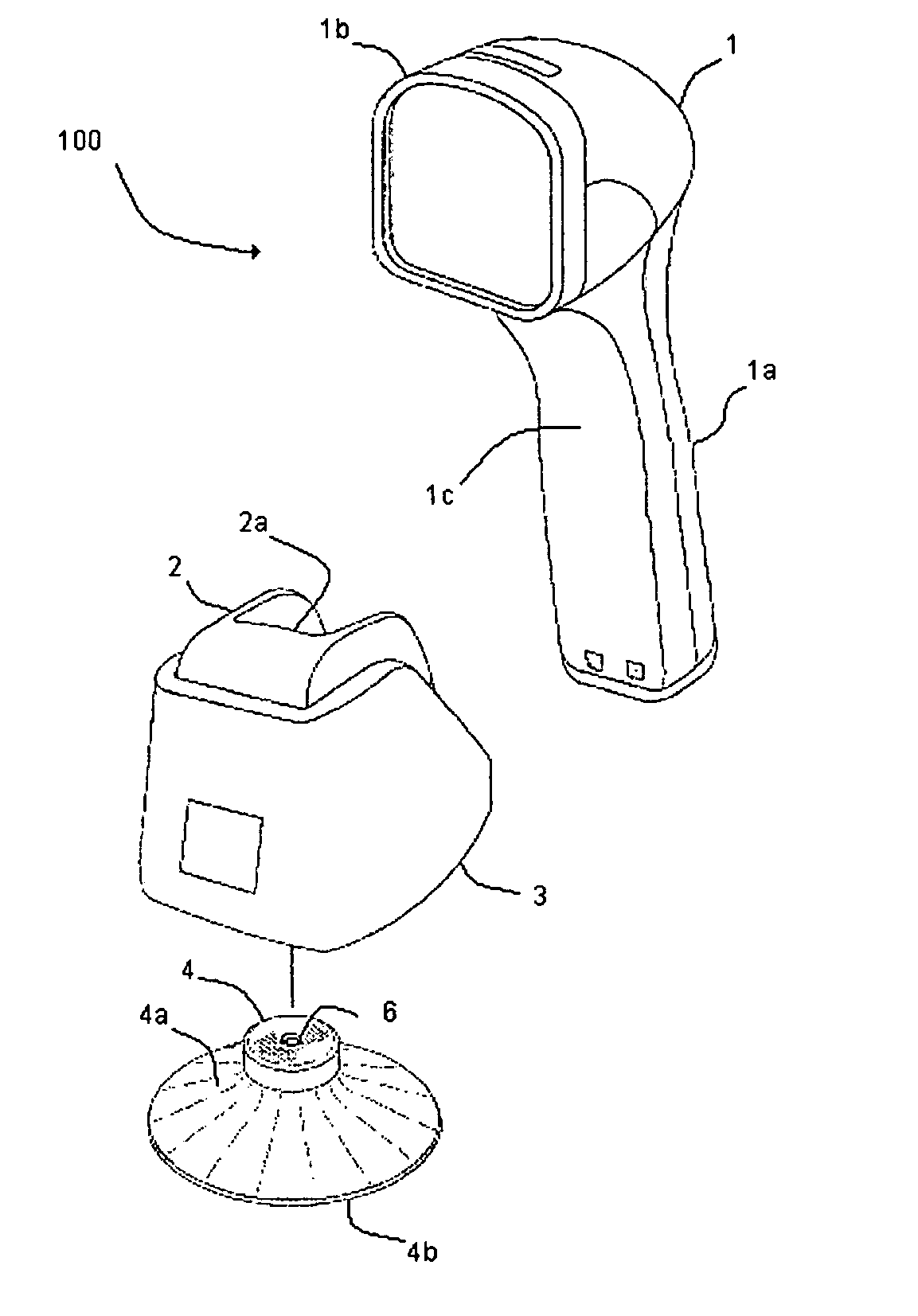
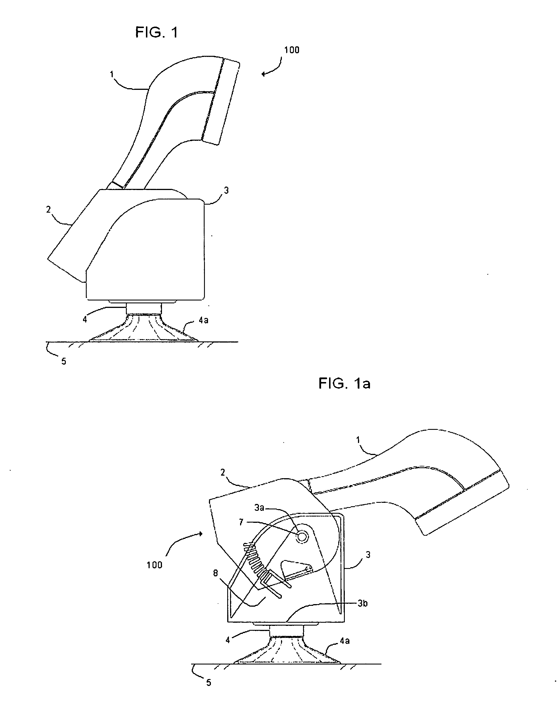
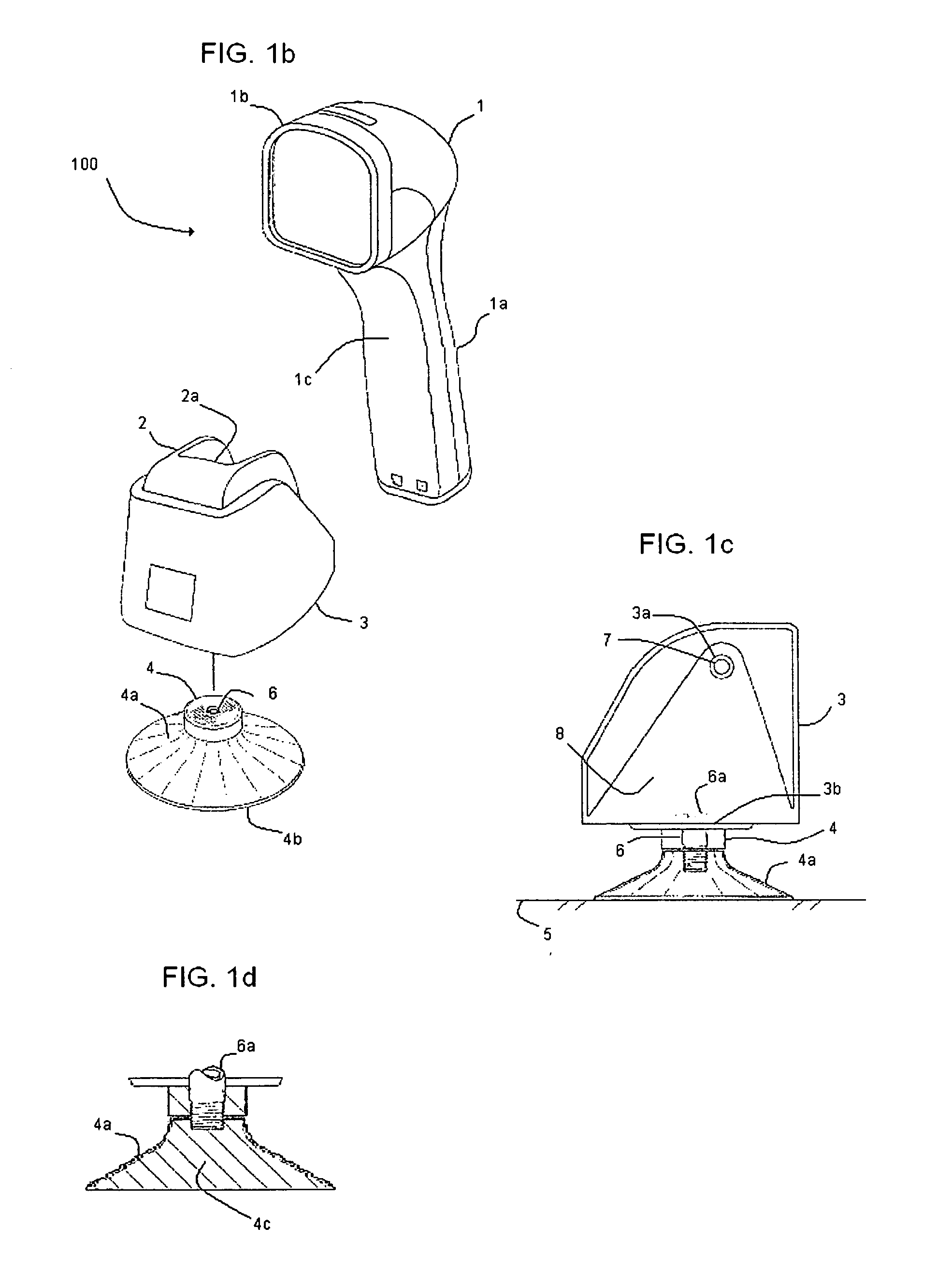
[0033] Referring to the figures in the accompanying Drawings, the various illustrative embodiments of the instant invention will be described in great detail, wherein like elements will be indicated using like reference numerals.

[0034] As shown in FIGS. 1 through 1d, a bar code reading system 100, according to the first illustrated embodiment of the instant invention, comprises a bar code scanner 1 operably associated with a cradle 2, a rigid connector 3 pivotally connected to said cradle 2 at first attachment point 3a, and a releasable-attachable base 4 mounted to said rigid connector 3 at a second attachment point 3b, wherein said releasable attachable base 4 is mounted to a flat surface 5 without modifying said flat surface 5. Bar code reading system 100 can be realized in a variety of different ways. For example, rigid connector 3 can be realized as a compact stand for support upon a countertop surface as shown FIG. 6, or it can be realized as a support for vertical wall-mounti...


PUM


Abstract

An improved bar code scanner is equipped with a releasable-attachable base for mounting said bar code scanner to a countertop without modifying said countertop. The releasable-attachable base is provided in the form of a suction-cup apparatus. If the suction-cup apparatus is mounted to the countertop, the bar code scanner becomes fixed to the countertop, alleviating the need for a permanent base, which would require modification to the countertop and irreversible damage to the countertop if the permanent base was ever removed due to an equipment upgrade or a change in operational requirements.

Description

BACKGROUND OF INVENTION [0001] 1. Field of the Invention [0002] The present invention relates to a suction mounted bar code symbol reading system, apparatus and stand for use in point-of-sale (POS) and other demanding scanning environments. [0003] 2. Brief Description of the Prior Art [0004] Optical bar code symbol reading devices (scanners) of various types have been developed for scanning and decoding bar code symbols. These scanners adapt readily to some operational environments, but present shortcomings when used in other situations. For example, consider system applications involving point-of-sale (POS) terminals in retail stores. Retail POS countertops are prime sales areas, attractive and well-kept countertops will result in increased shopper's confidence during a POS transaction, whereby this confidence may lead to increased customer loyalty and retention. [0005] Existing POS scanners generally fall into one of two general categories: hand-held or stationary. The first categ...

Claims


Application Information

Patent Timeline
Patent Type & Authority Applications(United States)
IPC IPC(8): G06K7/10
CPCG06K7/109G06K7/10881
Inventor TALLEY, HARRYGART, MATTHEW
Owner TALLEY HARRY
Why Eureka
Try Eureka