Laser beam scanning device employing a scanning element having a flexible photo-etched gap region disposed between an anchored base portion and a light beam deflecting portion having a natural frequency of oscillation tuned by the physical dimensions of said flexible photo-etched gap region and forcibly oscillated about a fixed pivot point at an electronically-controlled frequency of oscillation substantially different from said natural resonant frequency of oscillation

a scanning element and scanning element technology, applied in the direction of electromagnetic radiation sensing, dynamo-electric converter control, instruments, etc., can solve the problems of large and complex inability to produce prior art laser scanning mechanisms, and inability to accurately detect the position of the scanning element, so as to avoid shortcomings and drawbacks

Inactive Publication Date: 2005-04-05
METROLOGIC INSTR INC
View PDF29 Cites 18 Cited by
  • Summary
  • Abstract
  • Description
  • Claims
  • Application Information

AI Technical Summary

Benefits of technology

Accordingly, it is a primary object of the present invention to provide an improved laser beam scanning apparatus that avoids the shortcomings and drawbacks of prior art technologies.
Another object of the present invention is to provide such a laser beam scanning mechanism having ultra-low power consumption, and a low operating current.

Problems solved by technology

While such prior art scanning elements are durable, they are not without their shortcomings and drawbacks.
Such prior art laser scanning mechanisms are generally massive and large in comparison to the size of the scanning mirror supported thereby.
Prior art laser scanning mechanisms are generally difficult to produce, expensive to manufacture, difficult to precisely tune, and typically require an anti-shock mechanism to protect the scanning element from damage when dropped.
While laboring long and hard, Applicants have been unable to consistently manufacture in large volume and at low cost, a laser beam scanning mechanism based on such prior art design principles, without seriously sacrificing the operation and performance thereof.
Consequently, hitherto, Metrologic's ScanQuest® Laser Scanning Engine (Models 4110 and 4120), in which the above-described scanning mechanism is employed, could not be manufactured in high volume or at low cost.

Method used


Image

  • Laser beam scanning device employing a scanning element having a flexible photo-etched gap region disposed between an anchored base portion and a light beam deflecting portion having a natural frequency of oscillation tuned by the physical dimensions of said flexible photo-etched gap region and forcibly oscillated about a fixed pivot point at an electronically-controlled frequency of oscillation substantially different from said natural resonant frequency of oscillation
  • Laser beam scanning device employing a scanning element having a flexible photo-etched gap region disposed between an anchored base portion and a light beam deflecting portion having a natural frequency of oscillation tuned by the physical dimensions of said flexible photo-etched gap region and forcibly oscillated about a fixed pivot point at an electronically-controlled frequency of oscillation substantially different from said natural resonant frequency of oscillation
  • Laser beam scanning device employing a scanning element having a flexible photo-etched gap region disposed between an anchored base portion and a light beam deflecting portion having a natural frequency of oscillation tuned by the physical dimensions of said flexible photo-etched gap region and forcibly oscillated about a fixed pivot point at an electronically-controlled frequency of oscillation substantially different from said natural resonant frequency of oscillation

Examples


Embodiment Construction

The illustrative embodiments of the present invention will be described with reference to the figure drawings wherein like elements and structures are indicated by like reference numbers.

Over of the Laser Beam Scanning Mechanism Employed with Bar Code Symbol Readers of the Present Invention

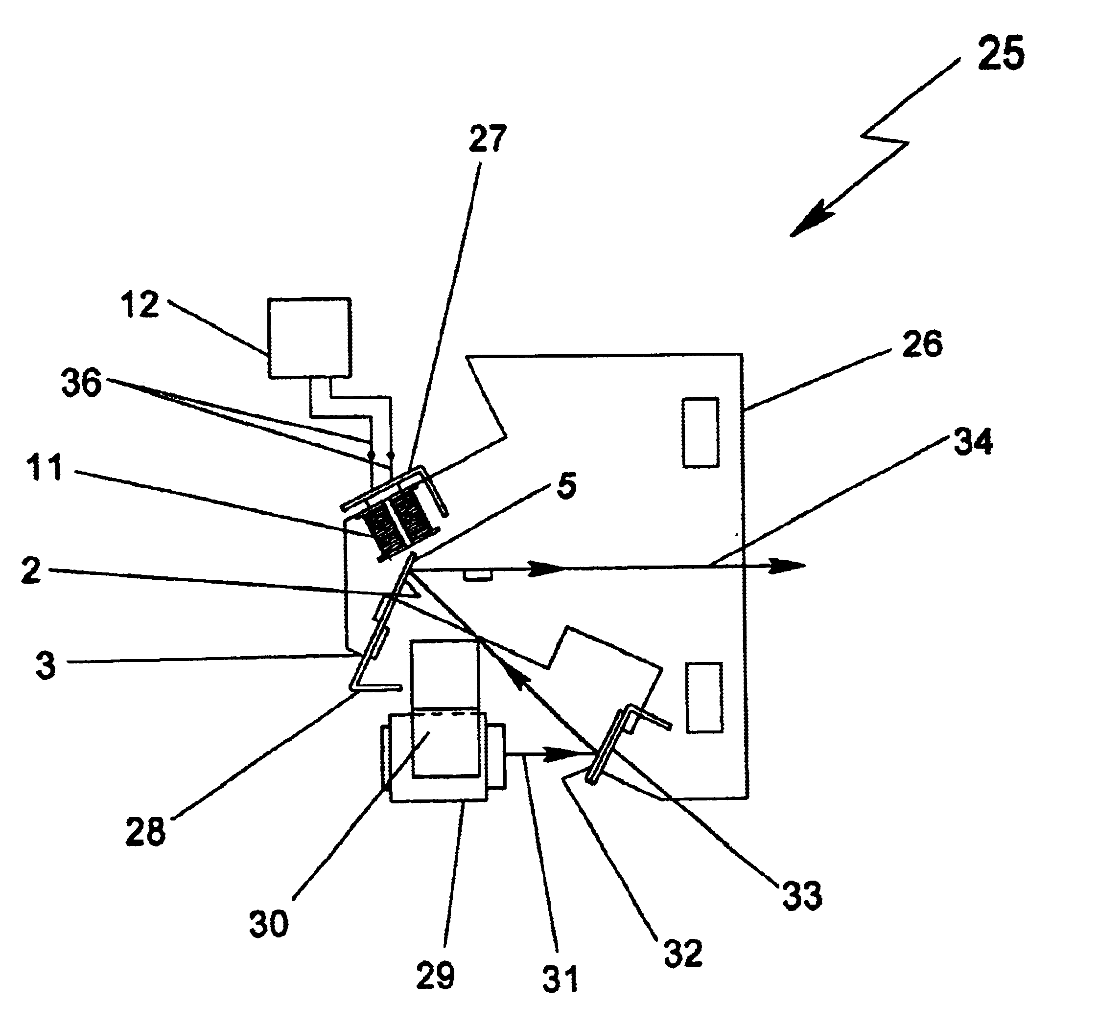
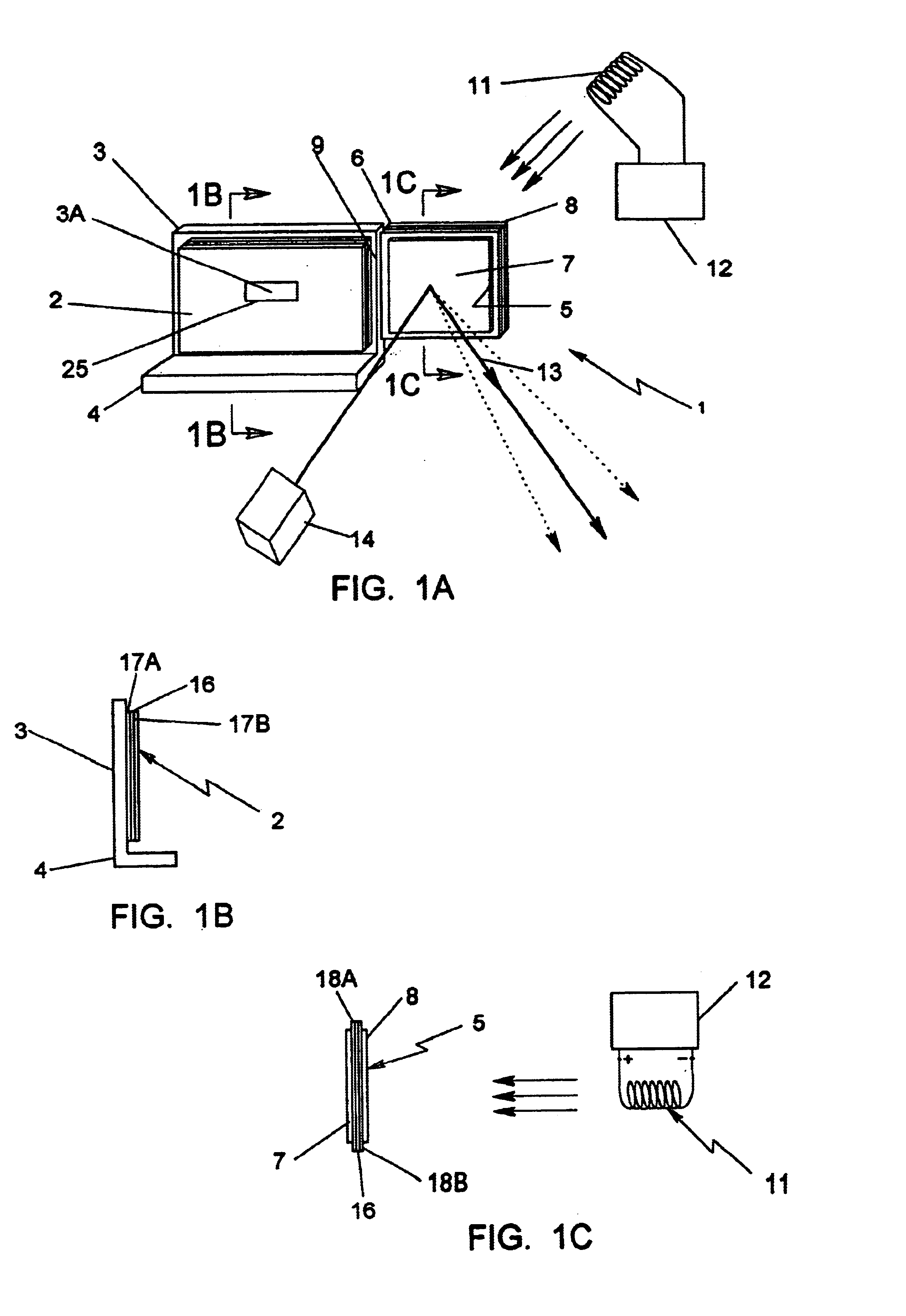
In FIG. 1A, the laser beam scanning mechanism of the present invention 1 is shown having a base portion 2 mounted (i.e., anchored) on a support structure 3 of an optical bench 4, and a laser beam deflecting portion 5 extending from the base portion, with a flexible gap portion 6 disposed therebetween.

As shown, the laser scan deflecting portion 5 bears a light deflecting element 7 on its front surface and a thin permanent magnet element 8 mounted on its rear surface. The light deflecting element 7 can be realized in a number of different ways, namely: as a light reflective element such as a mirror; as a light diffractive element such as a reflection or transmission hologram (i.e., HOE); as a light ...


PUM


Abstract

Disclosed is laser beam scanning apparatus in the form of an electronically-controlled mechanically-damped off-resonant laser beam scanning mechanism. The scanning mechanism comprises an etched scanning element having a small flexible gap region of closely-controlled dimensions disposed between an anchored base portion and a laser beam deflection portion The light beam deflection portion supports a permanent magnet and a light beam deflecting element (e.g., mirror or hologram). A reversible magnetic force field producing device (e.g., an electromagnet) is placed in close proximity with the permanent magnet so that it may be forcibly driven into oscillation in response to electrical current flowing through the electromagnet. The resonant frequency of oscillation of the laser beam deflecting portion relative to the anchored base portion is determined by the closely controlled dimensions of the flexible gap region set during manufacture. The steady-state frequency of oscillation of the laser beam deflecting portion is determined by the frequency of polarity reversal of the electromagnet, which is electronically controlled by the polarity of electrical current supplied thereto. In the illustrative embodiments, the forcing frequency of the electromagnet is selected to be at least ten percent off (i.e. greater or less than) the natural resonant frequency of the laser beam deflecting portion of manufacture to be any one of a very large range of values (e.g., 25-127 Hz) for use in both low-speed and high-speed laser scanning systems.

Description

BACKGROUND OF THE INVENTION1. Field of InventionThe present invention relates to laser scanning systems and more particularly, to electronically-controlled damped off-resonant mechanisms for reliably scanning laser beams during bar code symbol reading operations and the like.2. Brief Description of the Prior ArtLaser scanning bar code symbol scanners are widely used to read bar code symbols on products and packages for identification purposes. Many different techniques exist for scanning laser beams across objects.One commonly used beam scanning technique involves driving a resonant element bearing a mirror into oscillatory motion within a plane, while a laser beam is directed incident the mirror surface. As the resonant element oscillates, so too does the mirror, causing the incident laser beam to be scanned across a scanning field of substantially planar extent, as well as a bar code symbol disposed therewithin. In general, laser light reflected from the scanned bar code symbol is...

Claims


Application Information

Patent Timeline
Patent Type & Authority Patents(United States)
IPC IPC(8): G02B26/00G02B5/08G06K7/10G06F17/30
CPCG06K7/10643G06F17/30879G06F16/9554
Inventor BLAKE, ROBERT E.NAYLOR, CHARLES A.COLAVITO, STEVE J.AMUNDSEN, THOMASCARULLO, THOMASKNOWLES, C. HARRY
Owner METROLOGIC INSTR INC
Why Eureka
Try Eureka