Hydraulic control apparatus and hydraulic control method of vehicular automatic transmission

a technology of hydraulic control apparatus and automatic transmission, which is applied in the direction of gearing control, gearing elements, gearing, etc., can solve the problems of increasing repair man-hours at service plants, reducing controllability, and not identifying the site of failure, so as to reduce the considerable change in the speed change ratio

Active Publication Date: 2007-01-25
TOYOTA JIDOSHA KK
View PDF10 Cites 10 Cited by
  • Summary
  • Abstract
  • Description
  • Claims
  • Application Information

AI Technical Summary

Benefits of technology

[0019] As in the foregoing aspect, when there is a failure, the speed change stages that require, as a condition for the establishment thereof, the engagement of the hydraulic friction engagement device identified as having a failure by the identification portion are excluded in the determination of a speed change stage. This hydraulic control apparatus reduces the considerable change in the speed change ratio caused by occurrence of a failure during the running of the vehicle, and makes it possible to take off the vehicle after a temporary stop, and thus prevents, as much as possible, occurrence of impediments to the running of the vehicle.

Problems solved by technology

However, in the aforementioned hydraulic control apparatus of a vehicular automatic transmission, when a failure occurs, the site of occurrence of the failure is not identified.
Therefore, there are problems of degraded controllability during the running of the vehicle with a failure, and increased repair man-hours at service plants.

Method used


Image

  • Hydraulic control apparatus and hydraulic control method of vehicular automatic transmission
  • Hydraulic control apparatus and hydraulic control method of vehicular automatic transmission
  • Hydraulic control apparatus and hydraulic control method of vehicular automatic transmission

Examples


Embodiment Construction

[0031] Embodiments of the invention will be described in detail hereinafter with reference to the drawings.

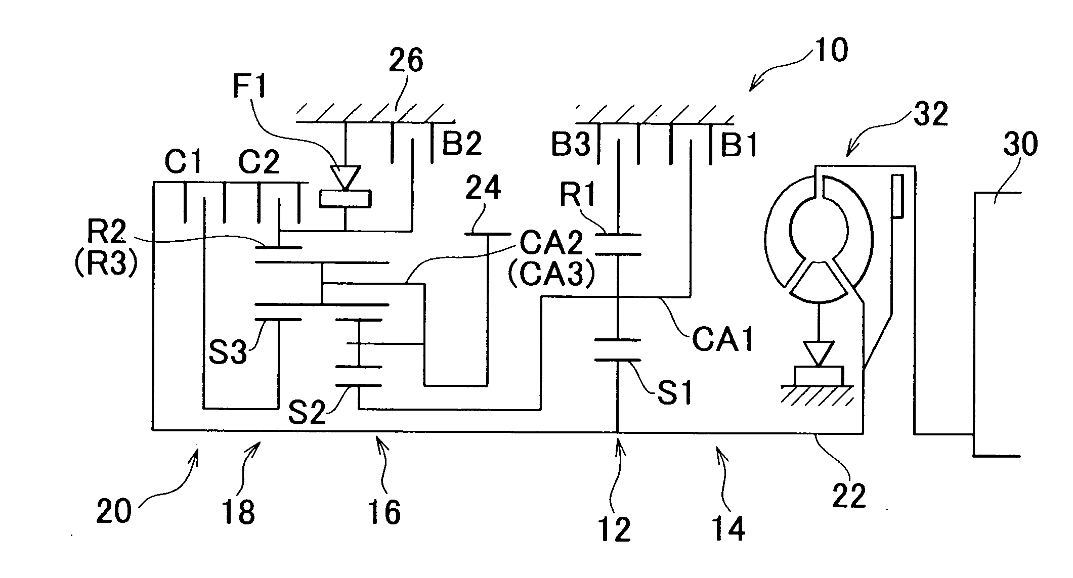
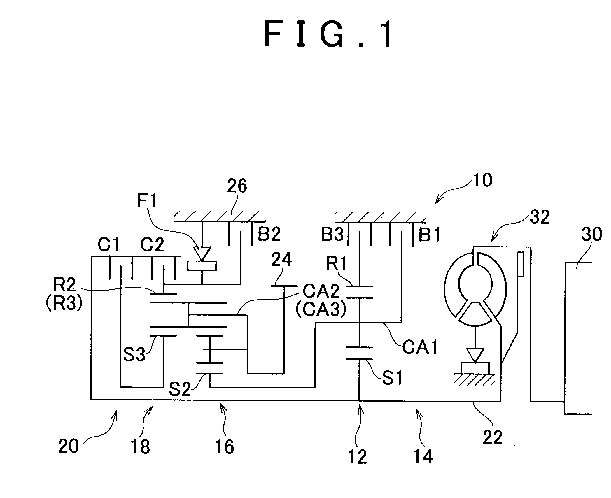
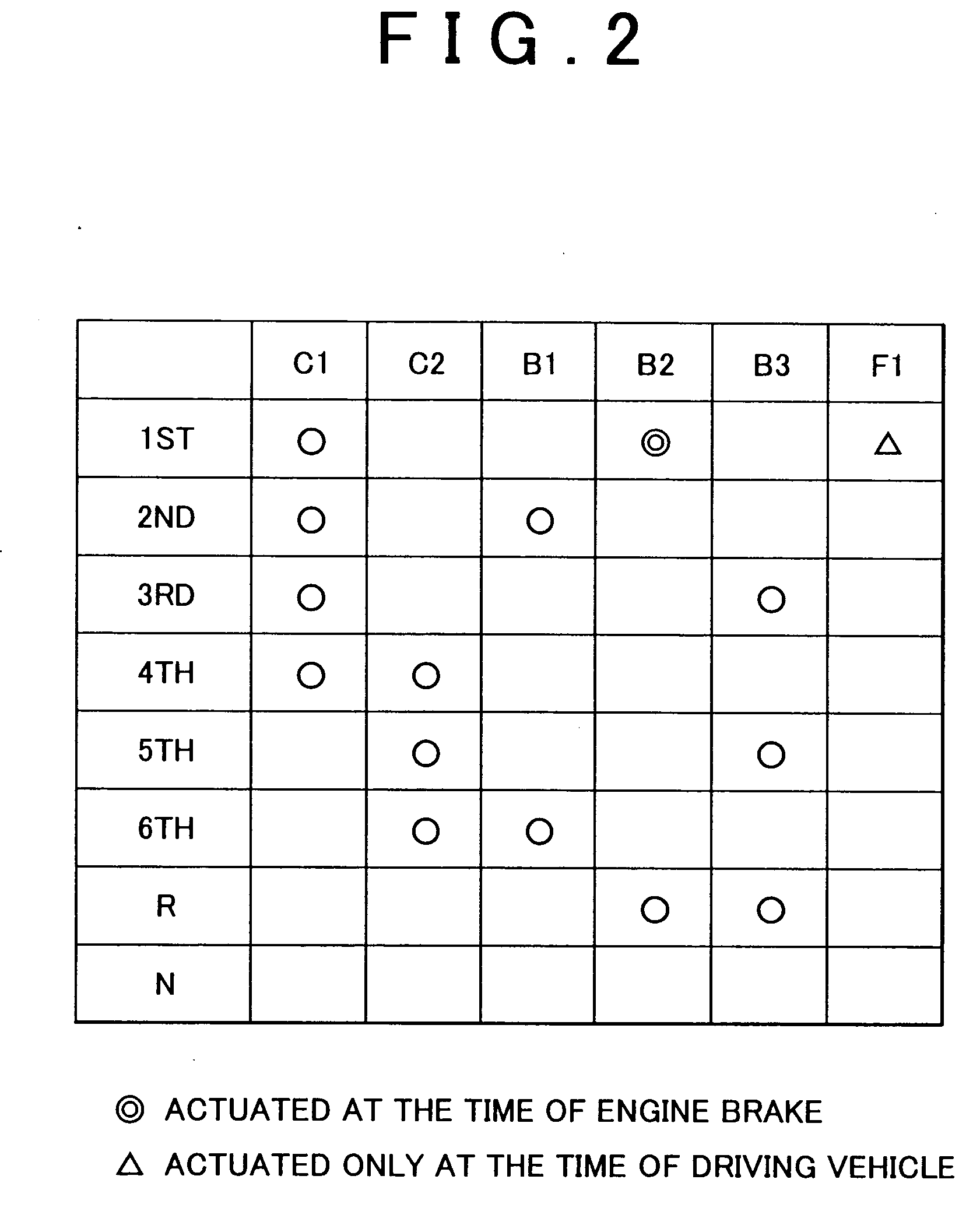
[0032]FIG. 1 is a skeleton diagram of a vehicular automatic transmission 10. FIG. 2 is an operation table illustrating the state of operation of engagement elements for establishing a plurality of speed change stages. This automatic transmission 10 is suitably used in an FF vehicle in which the automatic transmission is mounted in a right-to-left direction (transverse layout). The automatic transmission 10 has a first speed changer portion 14 that is formed mainly by a single-pinion type first planetary gear set 12, and a second speed changer portion 20 that is formed as a Ravigneaux type mainly by a double-pinion type second planetary gear set 16 and a single-pinion type third planetary gear set 18. The first speed changer portion 14 and the second speed changer portion 20 are provided on the same axis. The rotation of an input shaft 22 is changed in speed, and is output via ...


PUM


Abstract

A hydraulic control apparatus of a vehicular automatic transmission has a plurality of hydraulic friction engagement devices that are selectively engaged and released to establish a plurality of forward speed change stages of different speed change ratios. The forward speed change stages are achieved through engagement of predetermined friction engagement devices, of the plurality of friction engagement devices. If it is determined that a predetermined speed change stage corresponding to a predetermined shift output is not established, the hydraulic control apparatus identifies a hydraulic friction engagement device having a bad engagement that is a cause of the non-establishment of the predetermined speed change stage, on the basis of the state of engagement oil pressure of the predetermined friction engagement device.

Description

INCORPORATION BY REFERENCE [0001] The disclosure of Japanese Patent Application No. 2005-209014 filed on Jul. 19, 2005, including the specification, drawings and abstract, is incorporated herein by reference in its entirety. BACKGROUND OF THE INVENTION [0002] 1. Field of Invention [0003] The invention relates to a hydraulic control apparatus and a hydraulic control method of a vehicular automatic transmission which selectively achieve a plurality of speed change stages by combinations of engagement of a plurality of hydraulic friction engagement devices. More particularly, the invention relates to a technology that identifies a hydraulic friction engagement device having a bad engagement that has caused a failure in obtaining a speed change stage corresponding to a shift output, if such a failure occurs. [0004] 2. Description of Related Art [0005] The hydraulic control apparatus of an automatic transmission has hydraulic friction clutches and brakes used for speed shifts, and an ele...

Claims


Application Information

Patent Timeline
Patent Type & Authority Applications(United States)
IPC IPC(8): F16H31/00F16H59/40F16H59/42F16H59/68F16H61/12F16H61/68F16H61/684F16H61/686
CPCF16H59/68F16H61/12F16H61/686F16H2061/1208F16H2061/0209F16H2059/683F16H2061/1264F16H2061/1276F16H2061/122F16H61/00F16H61/4192
Inventor MORISE, MASARUMIYATA, HIDEKIKIMURA, HIROMICHIYASUDA, YUJI
Owner TOYOTA JIDOSHA KK
Why Eureka
Try Eureka