USB 2.0 HS voltage-mode transmitter with tuned termination resistance

Active Publication Date: 2007-02-01
SYNOPSYS INC
View PDF8 Cites 15 Cited by
  • Summary
  • Abstract
  • Description
  • Claims
  • Application Information

AI Technical Summary

Benefits of technology

[0011] To reduce power consumption in a high-speed USB transceiver, the conventional current-mode architecture can be replaced with a voltage-mode architecture. The voltage-mode architecture drives the USB signal using a voltage source, thereby eliminating the need for a voltage setting resistor co

Problems solved by technology

Unfortunately, the current-mode architecture used in conventional USB 2.0 transc

Method used


Image

  • USB 2.0 HS voltage-mode transmitter with tuned termination resistance
  • USB 2.0 HS voltage-mode transmitter with tuned termination resistance
  • USB 2.0 HS voltage-mode transmitter with tuned termination resistance

Examples


Example

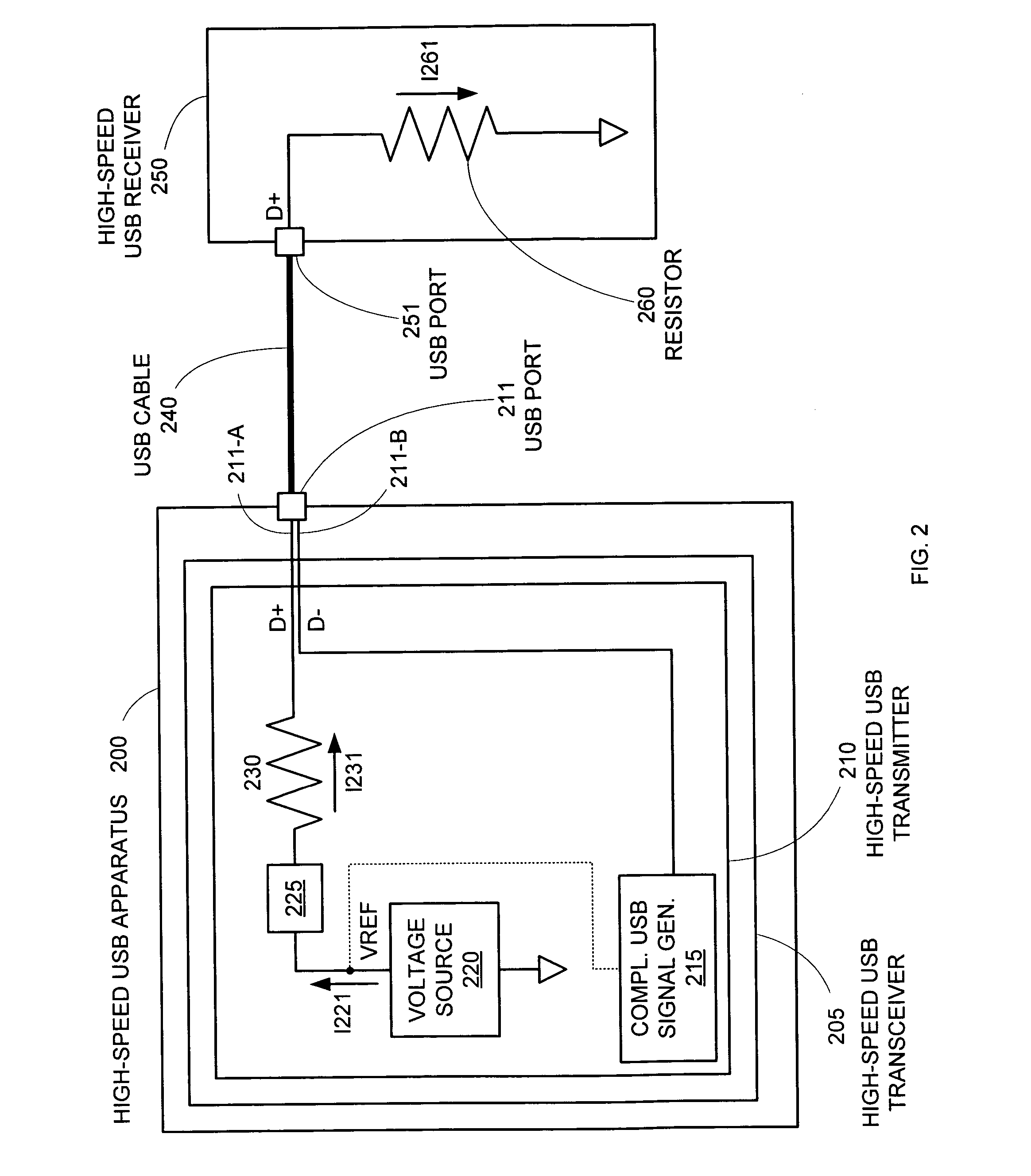
[0019] To reduce power consumption in a high-speed USB transceiver, the conventional current-mode architecture can be replaced with a voltage-mode architecture. The voltage-mode architecture drives the USB signal using a voltage source, thereby eliminating the need for a voltage setting resistor coupled to ground in the USB transceiver. As a result, the additional current path to ground provided by the voltage-setting resistor is eliminated, and current requirements for the voltage-mode USB transmitter can be effectively halved over the current requirements for a current-mode USB transmitter.

[0020]FIG. 2 shows an embodiment of a high-speed USB apparatus 200 (e.g., a computer, computer peripheral, digital cameral, PDA, or digital music player) based on a voltage-mode architecture. A USB port 211 on USB apparatus 200 is connected to a USB port 251 on a high-speed USB receiver 250 by a USB cable 240. As described above with respect to FIG. 1, high-speed USB receiver 250 (in a downstre...


PUM


Abstract

A high-speed universal serial bus (USB) transceiver includes a voltage-mode architecture for generating a USB signal. The voltage mode architecture reduces power consumption by reducing the current requirements for high-speed USB communications. The USB transceiver can include a reference voltage generator, a resistive element, and a switching element for completing and breaking a circuit including the reference voltage generator, the resistive element, and a data pin of a USB port to generate half of the differential USB signal (e.g., the D+ signal). A similar circuit can be used to generate the other half of the differential USB signal (i.e., the D− signal). The resistive element can be a set of parallel resistors in the transceiver, with the set of parallel resistors being specifically selected from a larger population of resistors to provide the specified resistance (45 Ω±10%) in the USB transceiver.

Description

BACKGROUND OF THE INVENTION [0001] 1. Field of the Invention [0002] The invention relates to the field of computer electronics, and in particular, to a system and method for enabling low-power universal serial bus communications. [0003] 2. Related Art [0004] The universal serial bus (USB) protocol is a popular communications protocol that allows a wide range of modern electronic devices and peripherals (e.g., scanners, digital cameras, personal digital assistants, and digital music players) to communicate with another peripheral. The present USB 2.0 specification (“Universal Serial Bus Specification”, Revision 2.0, Apr. 27, 2000) defines three signaling levels that can be supported by USB-compliant devices. The three levels include a low-speed mode operating at 1.5 Mbps at 3.3 V, a full-speed mode operating at 12 Mbps at 3.3 V, and a high-speed mode that signals at 480 Mbps at 400 mV. [0005] Modern high-speed USB 2.0-compliant devices include USB transceivers that are based on a cur...

Claims


Application Information

Patent Timeline
IPC IPC(8): H03B1/00
CPCH04L25/028H03K19/018557
Inventor HOWE, SCOTTTOFFOLON, DINO A.LACY, CAMERONCHONG, EUHAN
Owner SYNOPSYS INC
Why Eureka
Try Eureka