Fluidic optical devices

a technology of fluidic optical devices and liquids, which is applied in the direction of generators/motors, instruments, machines/engines, etc., can solve the problems of inconvenient form-factor of the whole system, difficulty in providing sufficient refractive index difference between the two liquids to provide adequate light-ray bending ability, and system disadvantage of remote location of pressurized fluid sources

Active Publication Date: 2007-02-08
HOLOCHIP
View PDF39 Cites 173 Cited by
  • Summary
  • Abstract
  • Description
  • Claims
  • Application Information

AI Technical Summary

Problems solved by technology

Although this yields a conveniently compact system, it is difficult to provide enough refractive index difference between the two liquids to provide adequate light-ray bending ability.
Although improved, that system still suffers from the disadvantage that the pressurized fluid source is located remotely.
This makes the form-factor of the whole system inconvenient.

Method used


Image

  • Fluidic optical devices
  • Fluidic optical devices
  • Fluidic optical devices

Examples


Embodiment Construction

[0121] Although the following detailed description contains many specific details for the purposes of illustration, anyone of ordinary skill in the art will appreciate that many variations and alterations to the following details are within the scope of the invention. Accordingly, the exemplary embodiments of the invention described below are set forth without any loss of generality to, and without imposing limitations upon, the claimed invention.

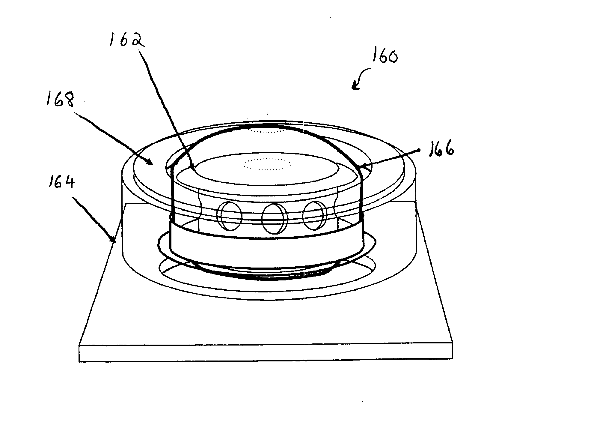
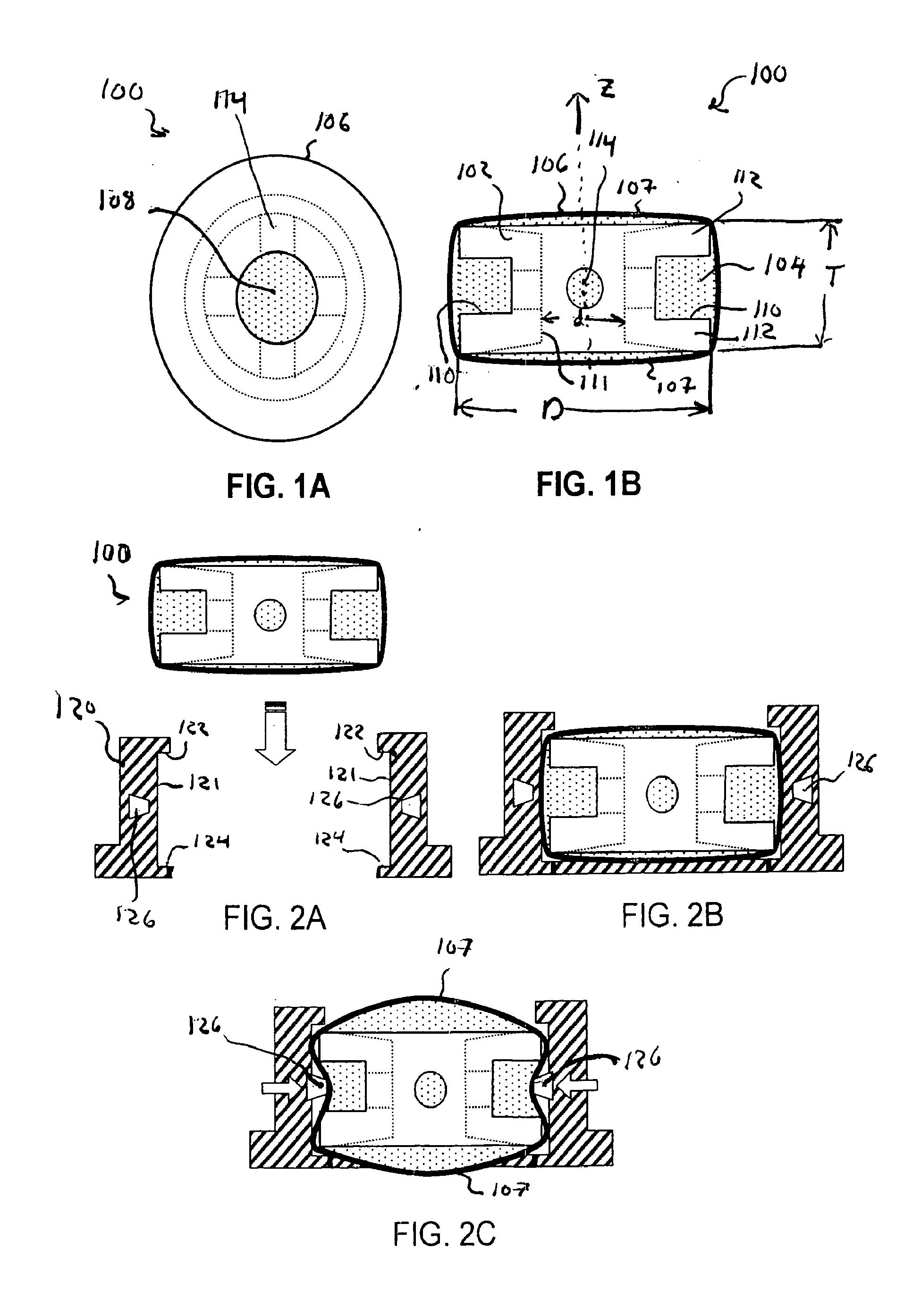
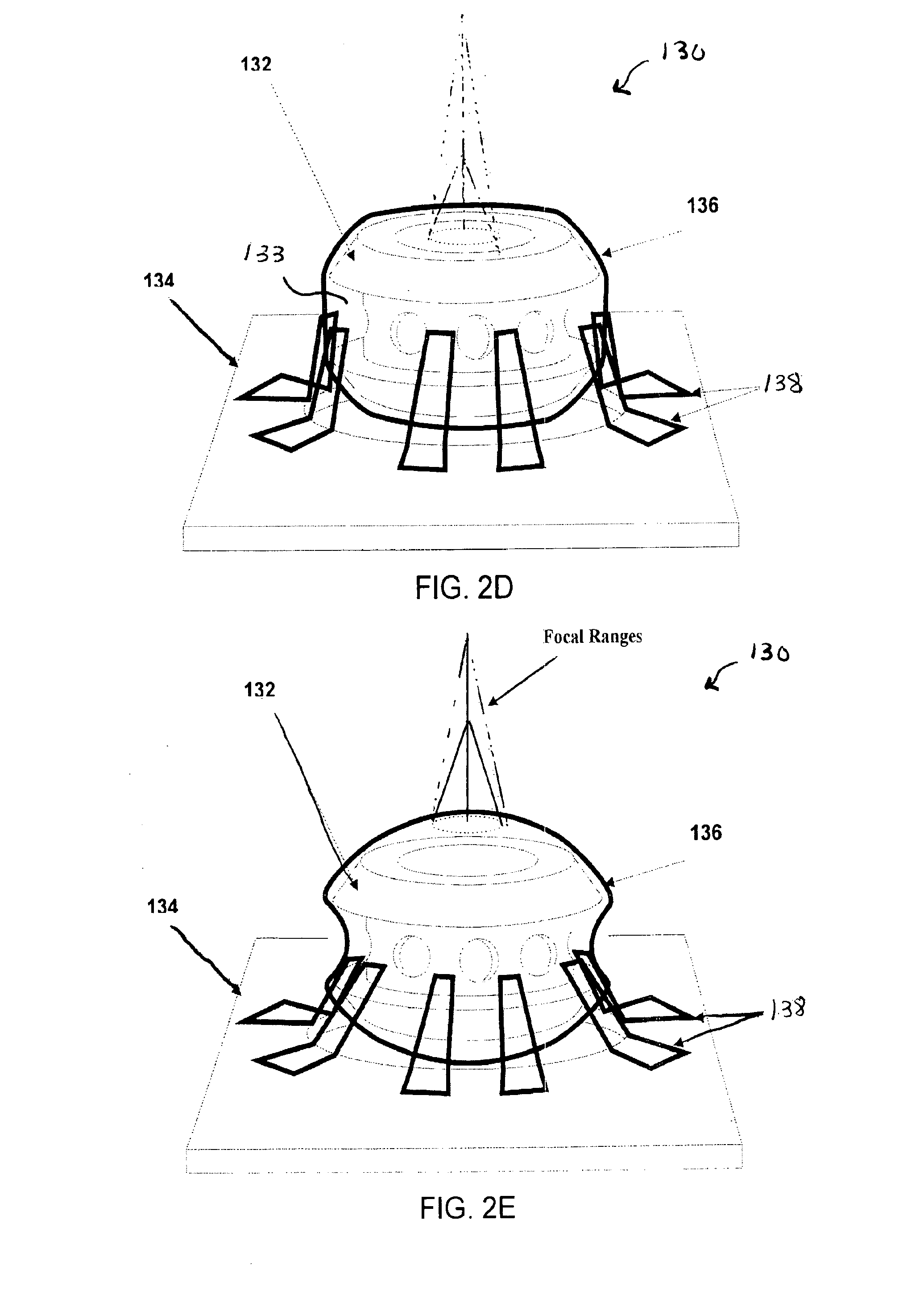
[0122] A common inventive thread in each of the preferred embodiments of this invention is a compact arrangement of the actuator structure and fluidic lens. The task of reducing the profile of the actuator is facilitated in part by judicious choice of its mechanical interface with the compliant fluidic lens. In order to achieve efficient adjustment of the focal length of the fluidic lens (for example, maximizing the range of focal power of the lens while minimizing the work, mechanical motion or stroke required by the actuator), some means...


PUM


Abstract

A fluidic optical device, systems utilizing fluidic optical devices, methods for manufacturing fluidic optical devices and actuators are disclosed.

Description

CROSS-REFERENCE TO RELATED APPLICATIONS [0001] This application claims priority to U.S. Provisional Patent Application 60 / 680,632 to Robert G. Batchko et al entitled “FLUIDIC OPTICAL DEVICES”, filed May 14, 2005, the entire disclosures of which are incorporated herein by reference. [0002] This application claims priority to U.S. Provisional Patent Application 60 / 683,072 to Robert G. Batchko et al entitled “FLUIDIC OPTICAL DEVICES”, filed May 21, 2005, the entire disclosures of which are incorporated herein by reference. [0003] This application claims priority to U.S. Provisional Patent Application 60 / 703,827 to Robert G. Batchko et al entitled “FLUIDIC OPTICAL DEVICES”, filed Jul. 29, 2005, the entire disclosures of which are incorporated herein by reference. [0004] This application claims priority to U.S. Provisional Patent Application 60 / 723,381 to Robert G. Batchko et al., filed Oct. 3, 2005, the entire disclosures of which are incorporated herein by reference. [0005] This applic...

Claims


Application Information

Patent Timeline
Patent Type & Authority Applications(United States)
IPC IPC(8): G02B3/12
CPCG02B26/005G02B3/14F03G7/065H02N2/002B33Y30/00B33Y80/00H10N30/2027B33Y50/02
Inventor BATCHKO, ROBERT G.MANSELL, JUSTIN D.SZILAGYI, ANDREICRABTREE, ALLEN F. IV
Owner HOLOCHIP
Why Eureka
Try Eureka