Gazing globes and other ornamental objects including light sources and light-activated materials

a technology of light-activated materials and ornamental objects, which is applied in the field of ornamental objects, can solve problems such as products that no longer glow, and achieve the effect of prolonging the operating period of light-activated materials and conserving battery power

Active Publication Date: 2007-02-08
RSR INDS
View PDF17 Cites 23 Cited by
  • Summary
  • Abstract
  • Description
  • Claims
  • Application Information

AI Technical Summary

Benefits of technology

[0004] This invention improves upon the existing art by providing a light source to extend the operating period of light-activated materials in gazing globes and other decorative or ornamental objects. In the preferred embodiment, a photoluminescent material, which may be phosphorescent or fluorescent, is included on or in the object. A light source of an appropriate wavelength causes the material(s) to glow for a longer period of time after the sun has gone down. Also in the preferred embodiment, a solar cell is used to charge a battery during the day, allowing for a completely self-contained system. A photocell is used to turn the light source on and off, thereby limiting illumination to dark periods, conserving battery power.

Problems solved by technology

One drawback with the approach just described is that after a few hours following sundown, the light-emitting capabilities of these materials falls off, resulting in a product which no longer glows as nighttime continues.

Method used


Image

  • Gazing globes and other ornamental objects including light sources and light-activated materials
  • Gazing globes and other ornamental objects including light sources and light-activated materials
  • Gazing globes and other ornamental objects including light sources and light-activated materials

Examples


Embodiment Construction

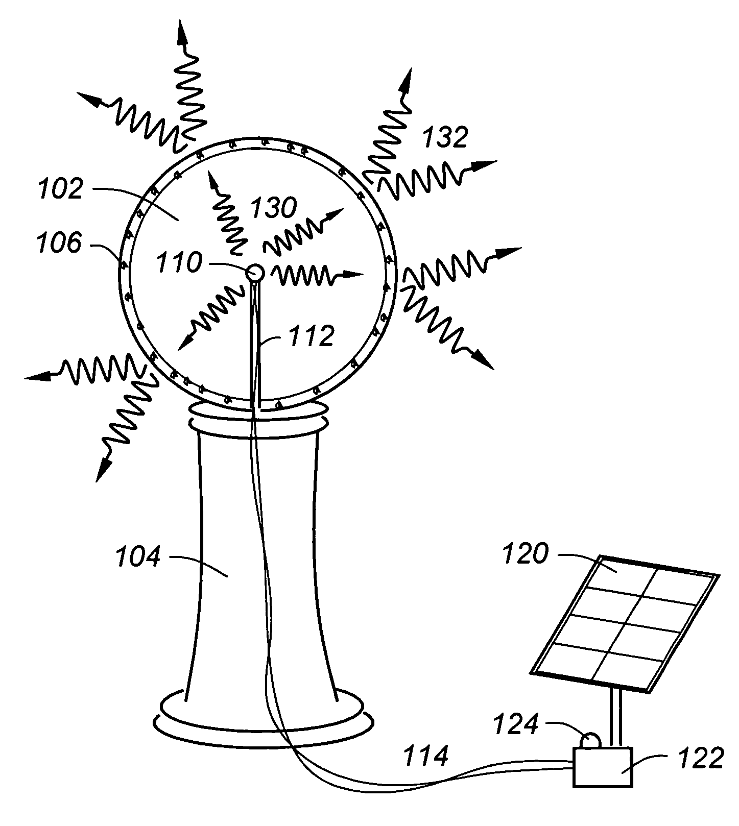
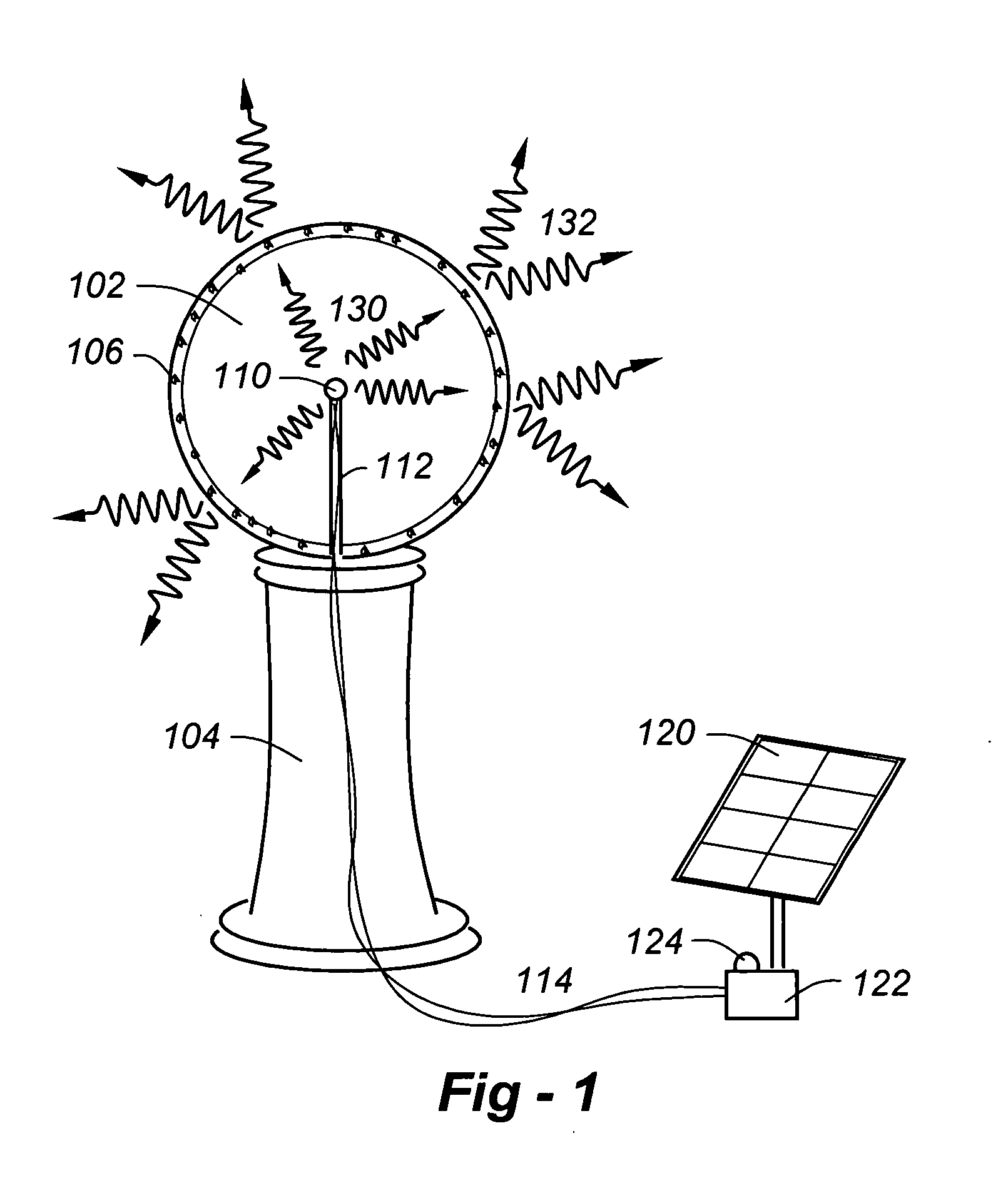
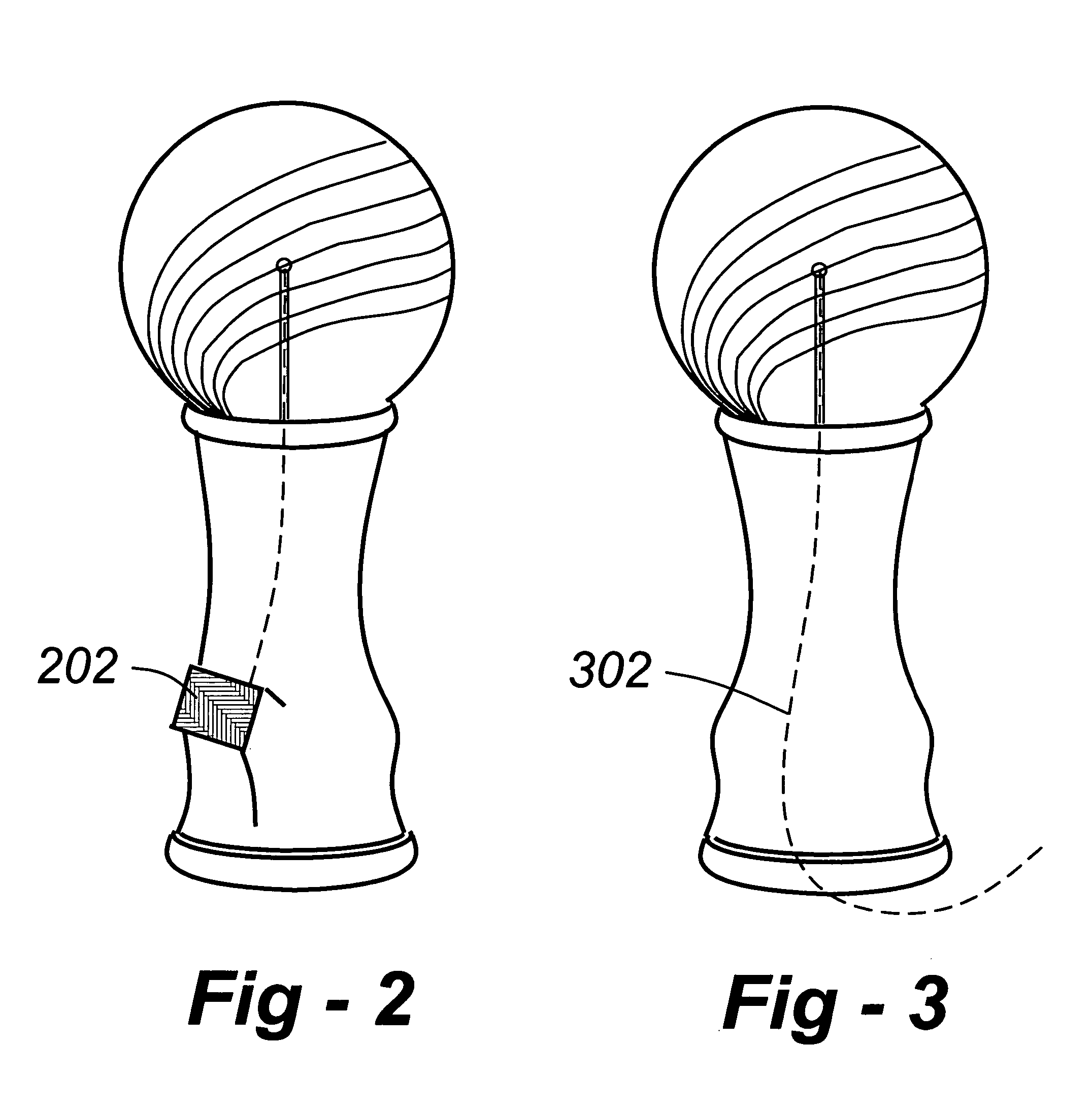
[0009]FIG. 1 is a drawing which shows the invention applied to a gazing globe with the understanding that the principles and methods described herein are equally applicable to other indoor / outdoor decorative fixtures, which will be apparent to those of skill in the art.

[0010] The device includes a globe 102 which may be solid or hollow, including particles 106 which receive light 130 from one or more sources 110, and emit light 132 after the light source has been removed. Such glow-in-the-dark substances may be photoluminescent, phosphorescent, fluorescent, etc. These substances may either be embedded with the sphere 102, or applied to the interior or exterior surfaces thereof, by whatever appropriate means are available. In the event that the globe 102 or other ornamental object is glass, the particles 106 may be included into the melt prior to solidification, or adhered to the inside of the globe (or outside of the globe) through appropriate adhesives. Suitable plastics, includin...


PUM

PropertyMeasurementUnit
transparentaaaaaaaaaa
translucentaaaaaaaaaa
photoluminescentaaaaaaaaaa

Abstract

A light source is used to extend the operating period of light-activated materials in gazing globes and other decorative or ornamental objects. A gazing globe according to the invention includes a hollow glass globe supported on a stand. Photoluminescent, fluorescent or phosphorescent material is deposited on, or embedded in, the globe. A light-emitting diode (LED) is supported within the globe to activate the material. A solar cell is used to charge one or more batteries, and a light detector is used to switch power from the battery to the source of light when a sufficient level of darkness is detected. A violet or ultraviolet LED may be used as the light source, with the solar cell is supported on the stand. The material deposited on, or embedded in, the globe may intentionally glow in a swirling pattern when activated.

Description

REFERENCE TO RELATED APPLICATION [0001] This application claims priority to U.S. Provisional Patent Application Ser. No. 60 / 693,361, filed Jun. 23, 2005, the entire content of which is incorporated herein by reference.FIELD OF THE INVENTION [0002] This invention relates generally to decorative objects and, in particular, gazing globes and other ornamental objects including light sources and light-activated materials. BACKGROUND OF THE INVENTION [0003] Pending U.S. Patent Application Ser. No. 20050003120 describes a method of fabricating glow-in-the-dark gazing globes or other objects, as well as the articles that result. The method comprises the steps of providing a hollow form having an inner wall made from a transparent or translucent material, the form including an aperture for gaining access to the interior thereof, and introducing one more photoluminescent pigments into the form through the aperture so that they cling to the inner wall. In alternative embodiments, the pigments ...

Claims


Application Information

Patent Timeline
Patent Type & Authority Applications(United States)
IPC IPC(8): F21V9/16
CPCB44C5/005F21S8/08F21S9/032F21Y2101/02F21V23/0442F21W2121/00F21V9/16Y10S362/809Y10S362/811Y10S362/80F21Y2115/10F21V3/12Y02B20/40F21V9/30F21S9/03F21V3/04H05B47/11
Inventor COHEN, RICHARD
Owner RSR INDS
Why Eureka
Try Eureka