Overload clutch

Inactive Publication Date: 2007-02-15
E EISENBEISS SOHNE MASCH UND PRAZISIONSZAHNRADERFAB
View PDF9 Cites 0 Cited by
  • Summary
  • Abstract
  • Description
  • Claims
  • Application Information

AI Technical Summary

Benefits of technology

[0003] The present invention is thus based on the object of implementing an overload clutch of the type described at the beginning in such way that the tolerance range provided for the safe triggering of the overload clutch upon occurrence of an overload may be decisively reduced.
[0005] Since, as a result of these measures, the energy required for adjusting the holding unit is applied independently of the maximum transmittable torque by a separate energy accumulator, the acquisition of the transmitted torque may be assigned separately by assemblies separate from the triggering of the clutch, which represents a significant requirement for maintaining narrow tolerance ranges for the triggering of the overload clutch. In addition, the holding unit comprises a switching unit which is actuated upon response of the overload clutch by an actuating drive impinged by the energy accumulator and releases the displacement path of the displaceably mounted clutch body, so that very small operating times may be ensured for the overload clutch. The energy required for disengaging the clutch body which is engaged may be provided in a known way through the torque active between the coupled clutch bodies, for example, if clutch teeth are provided between the clutch bodies which impinge the clutch bodies to disengage due to the torque to be transmitted like a wedge transmission. However, separate energy accumulators may also be provided for impinging the clutch bodies to disengage, which are necessary when the clutch engagement occurs via friction lamellae.

Problems solved by technology

These known overload clutches have the disadvantage above all that the clutch spring does not only determine the transmittable torque, but rather also the force with which the pressure ring must be impinged via the pressure transmission bodies to disengage the clutch engagement, which causes tolerance ranges for the delimitation of the maximum transmittable torque between the input and output clutch elements that cannot fulfill higher requirements on the triggering safety of such overload clutches.

Method used


Image

  • Overload clutch
  • Overload clutch
  • Overload clutch

Examples


Embodiment Construction

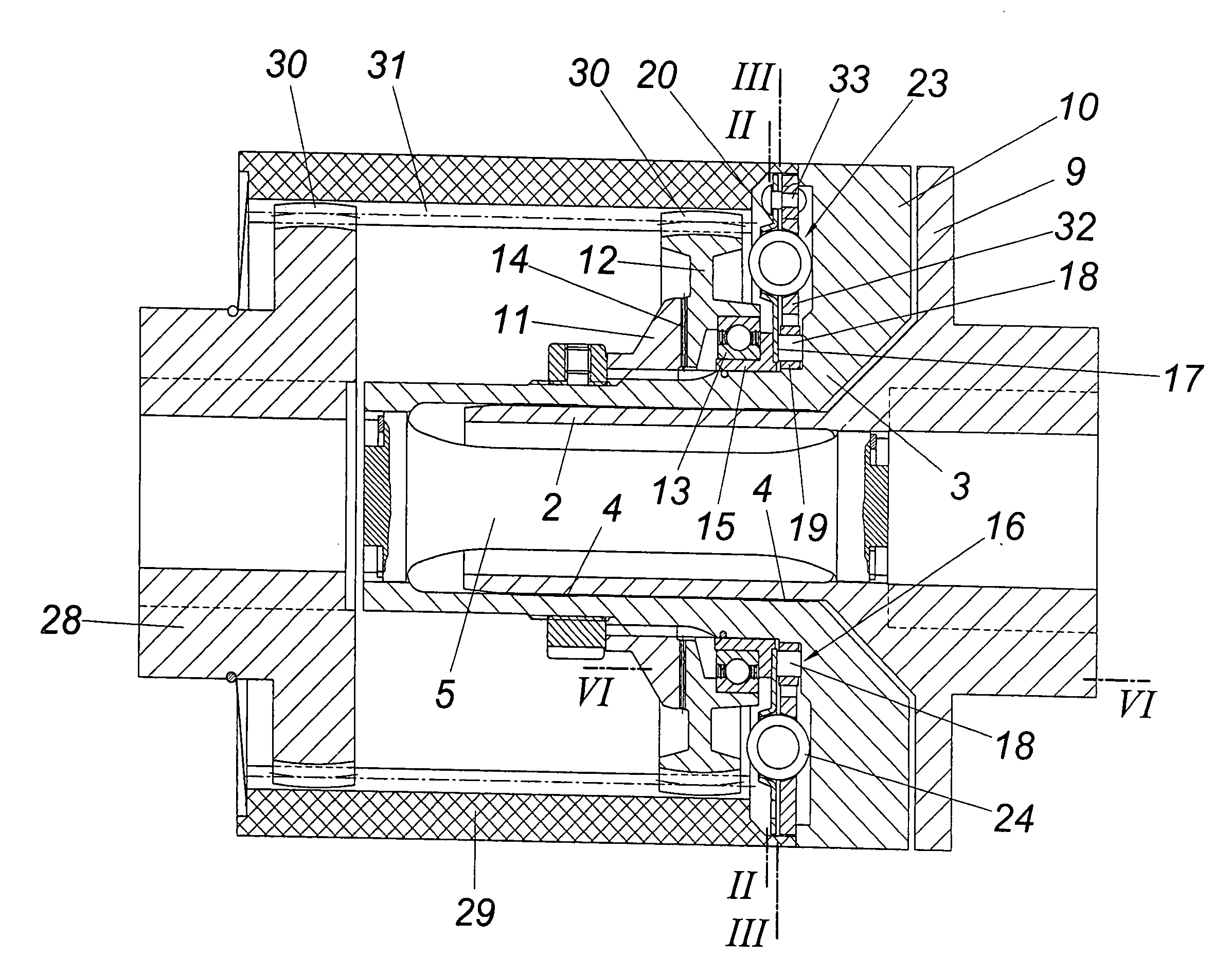
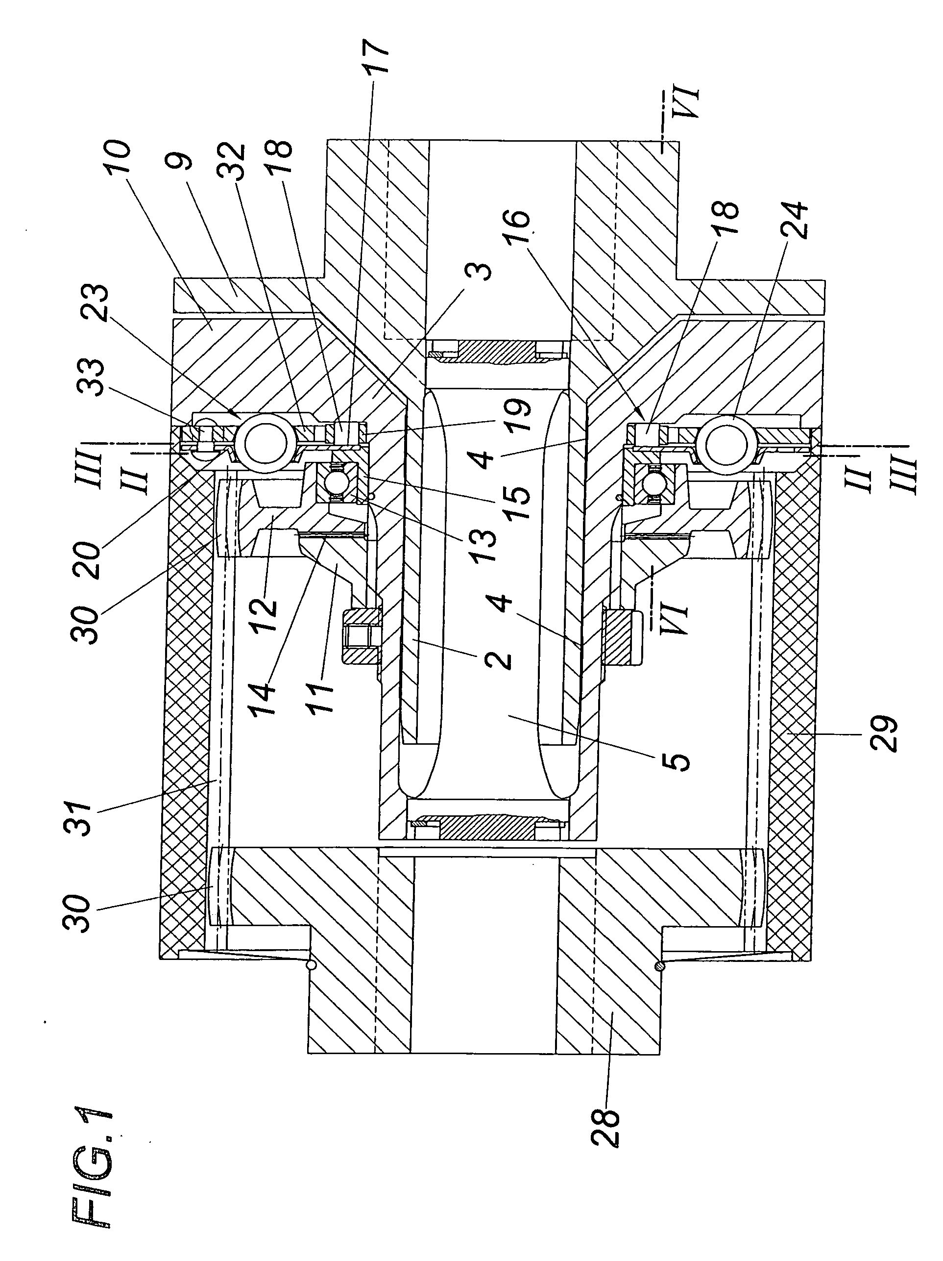
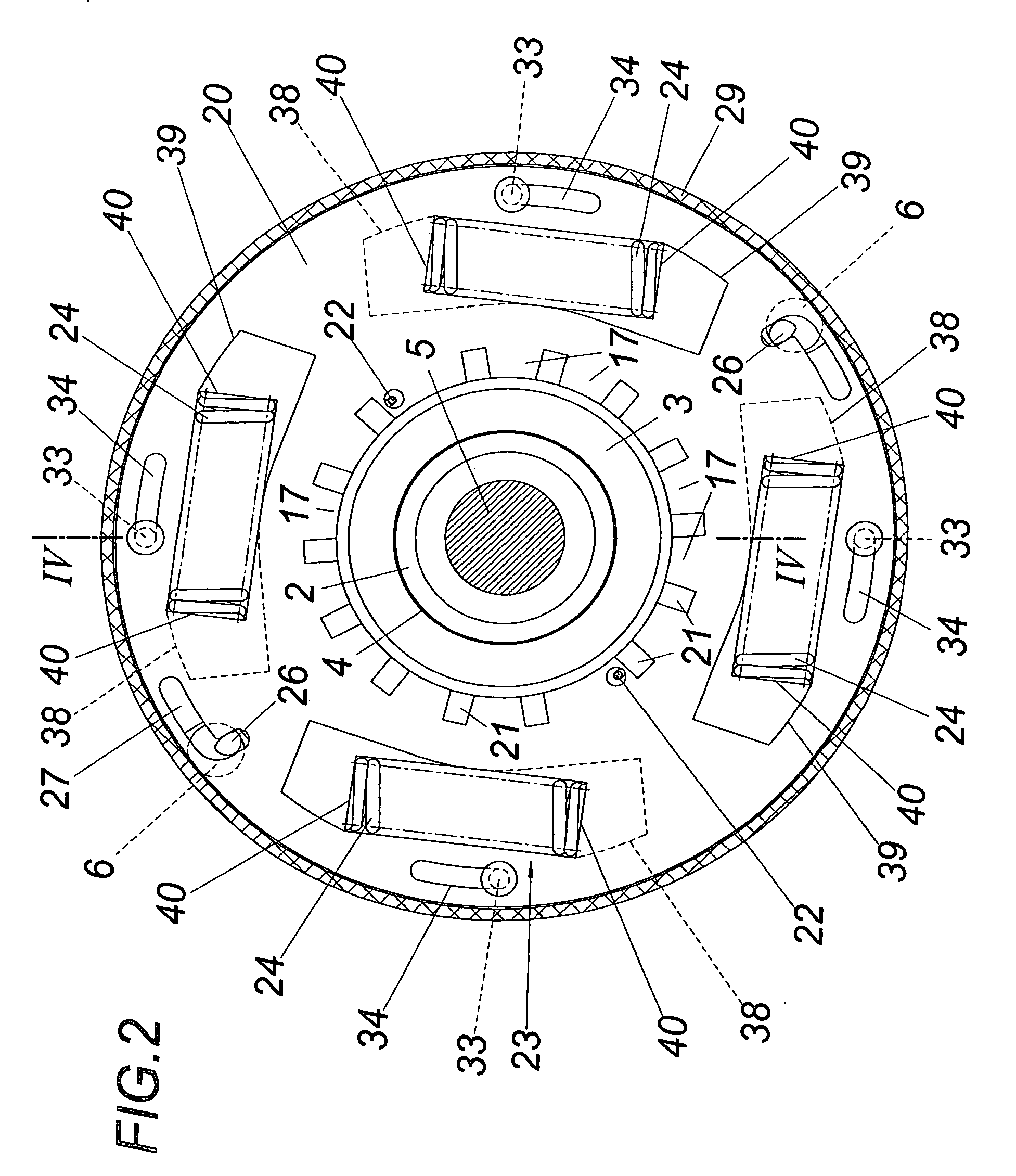
[0020] The overload clutch according to the exemplary embodiment shown has, on the drive side, a driving clutch element 1 connectable to an output shaft, which forms a bearing sleeve 2 for a clutch carrier 3, which is supported on the bearing sleeve 2 via a friction bearing 4. The clutch carrier 3 and the driving clutch element 1 are connected to drive one another via a pre-tensioned torsion rod 5. The torque pre-tension between the clutch element 1 and the clutch carrier 3 caused by the torsion rod 5 is absorbed by bolts 6, which are inserted into aligned holes 7, 8 of two diametrically opposite flanges 9, 10 of the clutch element 1 and the clutch carrier 3.

[0021] Two clutch bodies 11, 12 are positioned on the clutch carrier 3, of which one clutch body 11 is connected rotationally fixed to the clutch carrier 3, while the other clutch body 12 is mounted rotatably on the clutch carrier 3 via a roller bearing 13. This clutch body 12, which may be coupled to the clutch body 11 in the ...


PUM


Abstract

An overload clutch is described, having two clutch bodies (11, 12), one of which is mounted rotationally fixed and the other of which is mounted so it is rotatable on a clutch carrier (3), and which may be coupled in the axial direction, of which the axially displaceably mounted clutch body (12) is impinged to disengage, and having a holding unit adjustable as a function of the size of the transmitted torque for the clutch engagement. In order to provide advantageous triggering conditions, it is suggested that the holding unit comprise a switching unit (16), which releases the axial actuator travel of the displaceably mounted clutch body (12) and may be actuated by an actuating drive connected to an energy accumulator (23).

Description

1. FIELD OF THE INVENTION [0001] The present invention relates to an overload clutch having two clutch bodies, one of which is mounted rotationally fixed and the other of which is mounted rotatably on a clutch carrier, and which may be coupled in the axial direction, of which the axially displaceably mounted clutch body is impinged to disengage, and having a holding unit, which is adjustable as a function of the size of the torque transmitted, for the clutch engagement. 2. DESCRIPTION OF THE PRIOR ART [0002] In a known overload clutch of this type (DE 43 00 952 A1), the clutch carrier, which is implemented as a hub, carries a claw collar having radially oriented claws. This claw collar, which is connected rotationally fixed to the clutch carrier, has a claw collar having axially oriented claws assigned to it, which is mounted on the clutch carrier so it is freely rotatable via a ball bearing. Spherical pressure transmission bodies are provided between the claws of the two claw rings...

Claims


Application Information

Patent Timeline
IPC IPC(8): F16D7/02F16D43/20F16D7/04
CPCF16D7/044
Inventor GUNTER, JURGENS
Owner E EISENBEISS SOHNE MASCH UND PRAZISIONSZAHNRADERFAB
Why Eureka
Try Eureka