Sheet feeding unit, sheet feeding apparatus, and image forming apparatus

Inactive Publication Date: 2007-03-01
CANON KK
View PDF10 Cites 17 Cited by
  • Summary
  • Abstract
  • Description
  • Claims
  • Application Information

AI Technical Summary

Benefits of technology

[0019] The present invention is directed to a sheet feeing apparatus that makes it possible to apply the air adhesion elimination to, for example, image forming apparatuses for office use.

Problems solved by technology

In image forming apparatuses such as photocopiers and printers, cut sheets of paper that can be continuously fed are normally limited to sheets of high-quality paper and normal paper designated by photocopier manufacturers.
However, in the case of sheets that are formed of a resin material that tends to be electrically charged, such as OHP sheets and sheets of art film, in a dry environment, the surfaces of the sheets are gradually charged due to friction therebetween during a feeding operation.
Therefore, failure in pickup or double feeding can occur.
Therefore, in the conventional separation techniques, failure in pickup or double feeding can occur.
Therefore, in the conventional separation techniques, such special sheets can fail to be separated.
This can weaken the adhesive force particularly between sheets of coated paper under high humidity.
Therefore, the feeding apparatus cannot be applied to relatively low and medium class models to which a large feeding deck cannot be attached, and models for office use whose installation space is limited.
If such models use highly adhesive sheets, the sheets can fail to be separated and double feeding can occur.

Method used


Image

  • Sheet feeding unit, sheet feeding apparatus, and image forming apparatus
  • Sheet feeding unit, sheet feeding apparatus, and image forming apparatus
  • Sheet feeding unit, sheet feeding apparatus, and image forming apparatus

Examples


first exemplary embodiment

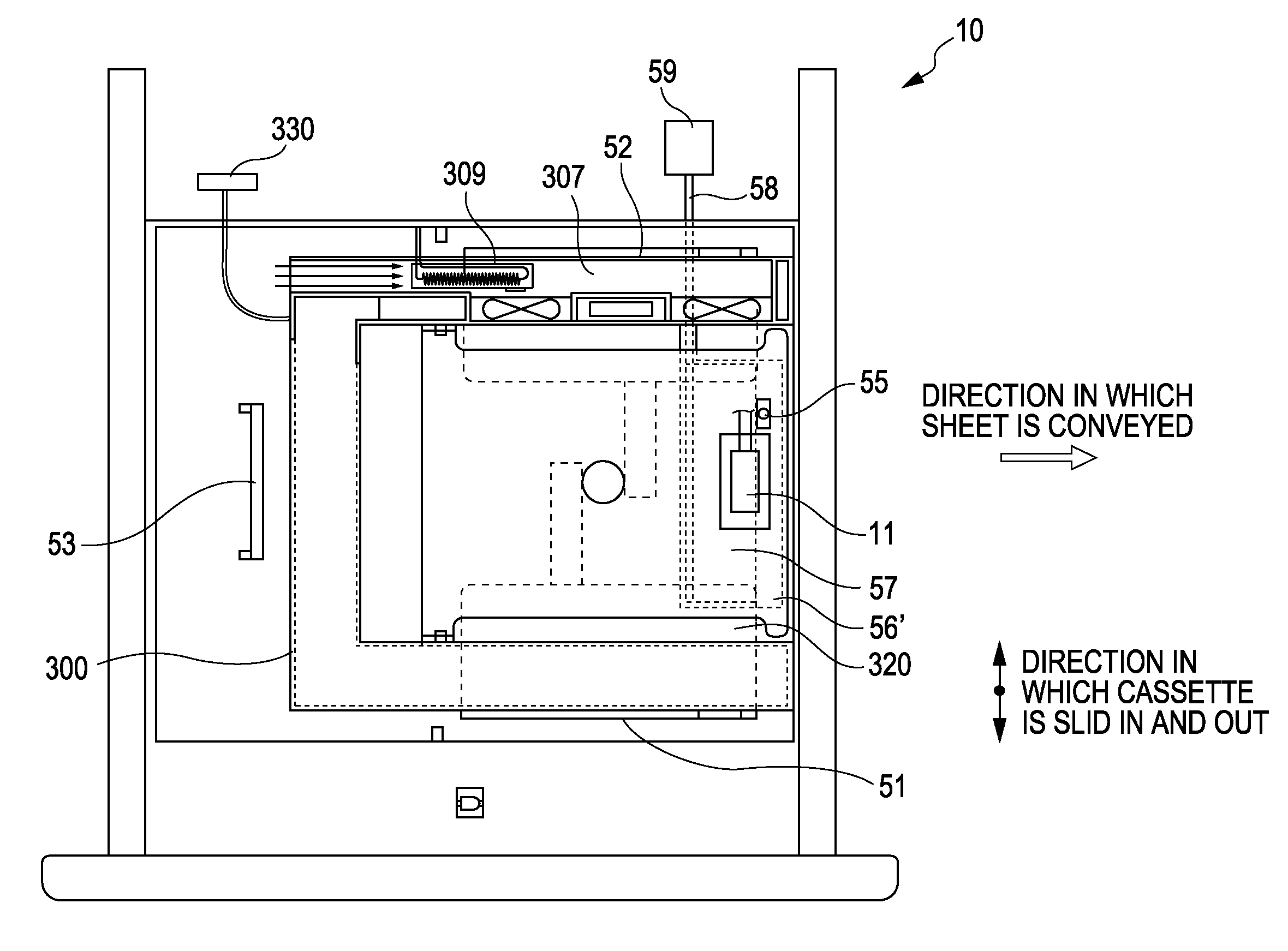
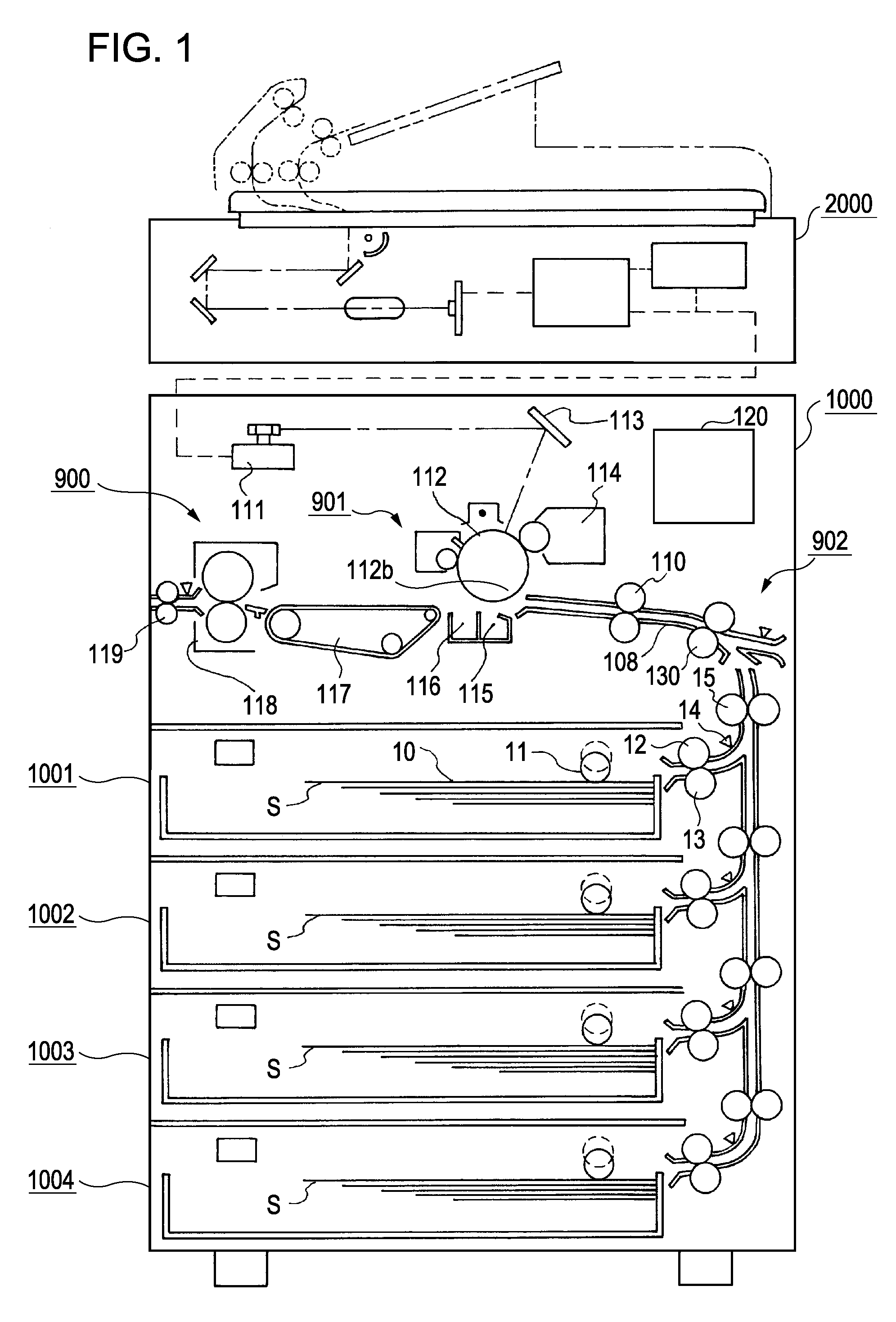
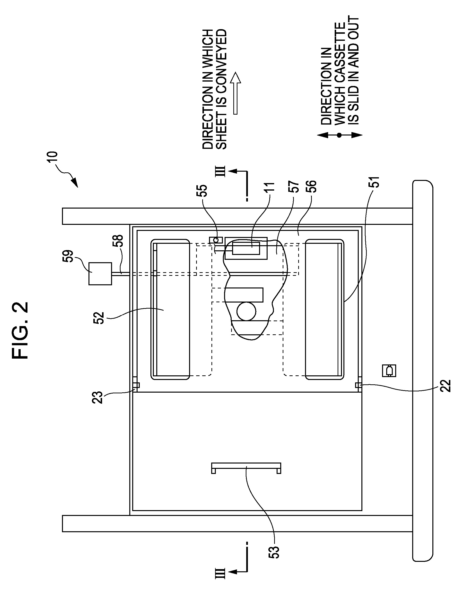
[0048] As shown in FIG. 1, the sheet feeding apparatus 1001 of the first embodiment includes a pickup roller 11 and a separating section. The pickup roller 11 serves as a sheet feeding member that feeds sheets S loaded in a sheet cassette 10. The separating section includes a feed roller 12 and a retard roller 13 that rotates in the opposite direction from the feed roller 12. The pickup roller 11 moves up and down and rotates at a predetermined time. The sheets S in the sheet cassette 10 are separated and fed one at a time by the pickup roller 11 and the separating section. A feed sensor 14 is provided on the downstream side and in the vicinity of the feed roller 12 and the retard roller 13. This feed sensor 14 can detect the passage of the sheet S.

[0049] The sheet cassette 10 is detachably attached to the sheet feeding apparatus 1001. When sheets that are hard to separate are used, a hereinafter-described sheet feeding unit is attached to the sheet cassette 10, and the sheets are ...

second exemplary embodiment

[0082] In the first embodiment, air is taken in through the air intake 308 of the sheet feeding assisting unit 300 and is blown against the side surface of the stack of sheets in the sheet loading space 320 through the blowing ports 303a and 303b. However, the air blown out through the blowing ports 303a and 303b may be circulated in the sheet feeding assisting unit 300. In the description of the sheet feeding apparatus of the second embodiment, only the differences from the first embodiment will be described in detail, and the description of components in common with the first embodiment will be omitted.

[0083] As shown in FIG. 10, the inner wall 302 opposite the blowing ports 303a and 303b is provided with exhaust ports 302a and 302b, and the case 301 is provided with a circulation duct 340 in which air circulates. The air heated by the air heating mechanism 309 passes through the circulation duct 340 as shown by arrows and is repeatedly supplied to the sheet loading space 320. Th...

third exemplary embodiment

[0094] Next, a third embodiment will be described with reference to FIGS. 12 to 15. In the description of the sheet feeding apparatus of the third embodiment, only the differences from the first embodiment will be described in detail, and the description of components in common with the first embodiment will be omitted.

[0095]FIG. 12 is a horizontal sectional view showing the structure of a sheet feeding assisting unit 400 for feeding sheets difficult to separate, such as heavy paper and coated paper. FIG. 13 is a perspective view of the sheet feeding assisting unit 400. FIGS. 14 and 15 are plan views showing a sheet cassette 10 in which the sheet feeding assisting unit 400 is installed.

[0096] The case 401 of the sheet feeding assisting unit 400 is rectangular-parallelepiped-shaped and is a size such that it can be installed in the sheet cassette. The sheet feeding assisting unit 400 has an air intake 408, a heater 409, a duct 407, fans 405 and 406, and blowing ports 403a and 403b....


PUM


Abstract

A feeding unit is detachably attached to a sheet cassette in which sheets are loaded. The feeding unit includes a sheet tray on which sheets are loaded, and a fan for blowing air against the side surface of a stack of sheets loaded on the sheet tray, the sheet tray and the fan being held in a case.

Description

BACKGROUND OF THE INVENTION [0001] 1. Field of the Invention [0002] The present invention relates to a sheet feeding unit, a sheet feeding apparatus, and an image forming apparatus for one-by-one feeding sheets that tend to stick to each other. [0003] 2. Description of the Related Art [0004] In image forming apparatuses such as photocopiers and printers, cut sheets of paper that can be continuously fed are normally limited to sheets of high-quality paper and normal paper designated by photocopier manufacturers. In order to separate and feed such sheets one-by-one, various frictional separation techniques, for example, a retard roller separation technique and a separation pad technique have been used. [0005] The retard roller separation technique will be described. A pickup roller is in contact with the uppermost sheet of a stack of sheets. A feed roller is provided on the downstream side of the pickup roller in the sheet feeding direction. A separation roller is in contact with the ...

Claims


Application Information

Patent Timeline
IPC IPC(8): B65H3/14
CPCB65H3/48B65H1/08
Inventor KOGA, HIROTOIMAI, YUSUKEHIURA, HIROSHI
Owner CANON KK
Why Eureka
Try Eureka