Electrical Connector

a technology of electrical connectors and connectors, applied in the direction of coupling device connections, coupling protective earth/shielding arrangements, two-part coupling devices, etc., can solve the problems of cb>1/b> and cb>2/b>, and achieve the effect of avoiding the occurrence of cb>2/b>

Inactive Publication Date: 2007-03-01
TYCO ELECTRONICS JAPAN GK
View PDF9 Cites 17 Cited by
  • Summary
  • Abstract
  • Description
  • Claims
  • Application Information

AI Technical Summary

Benefits of technology

[0013] It is an object of the present invention to provide a receptacle and a plug that are equipped with power supply contacts such that incorrect mating does not result in an unintended combination.

Problems solved by technology

On the other hand, among USB connectors, a USB-standard B-receptacle and a USB-standard B-plug are not equipped with power supply contacts.
Thus, proper positioning of the power supply pin sockets C1, C2 is difficult.
Moreover, because voltage-receiving pins P1, P2 inside the insulative housing of the plug 500 protrude toward the mating face, not only is there a lack of interchangeability with the USB-standard B-plug, but if the plug 500 is accidentally inserted into the USB-standard B-receptacle, the voltage-receiving pins P1, P2 will collide with the protruding member inside the recessed mating member of the USB-standard B-receptacle and may be damaged or may be caused to short-circuit.

Method used


Image

  • Electrical Connector
  • Electrical Connector
  • Electrical Connector

Examples


Embodiment Construction

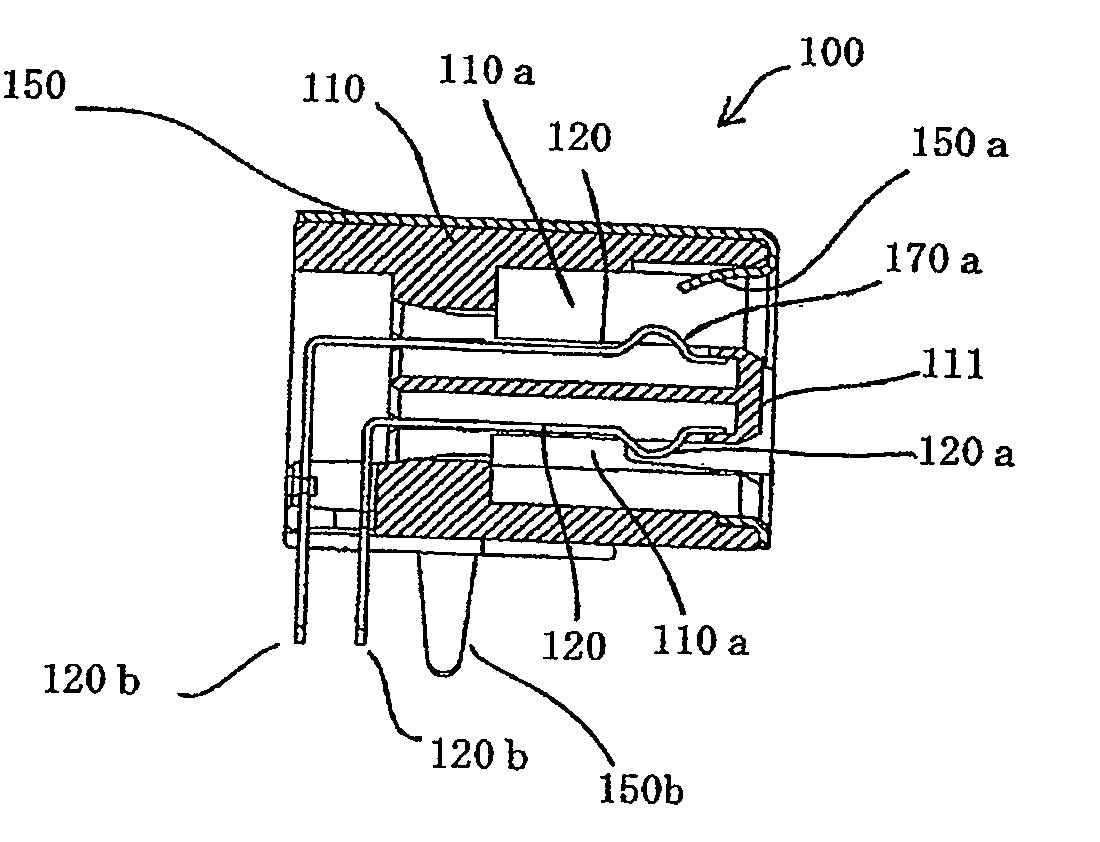
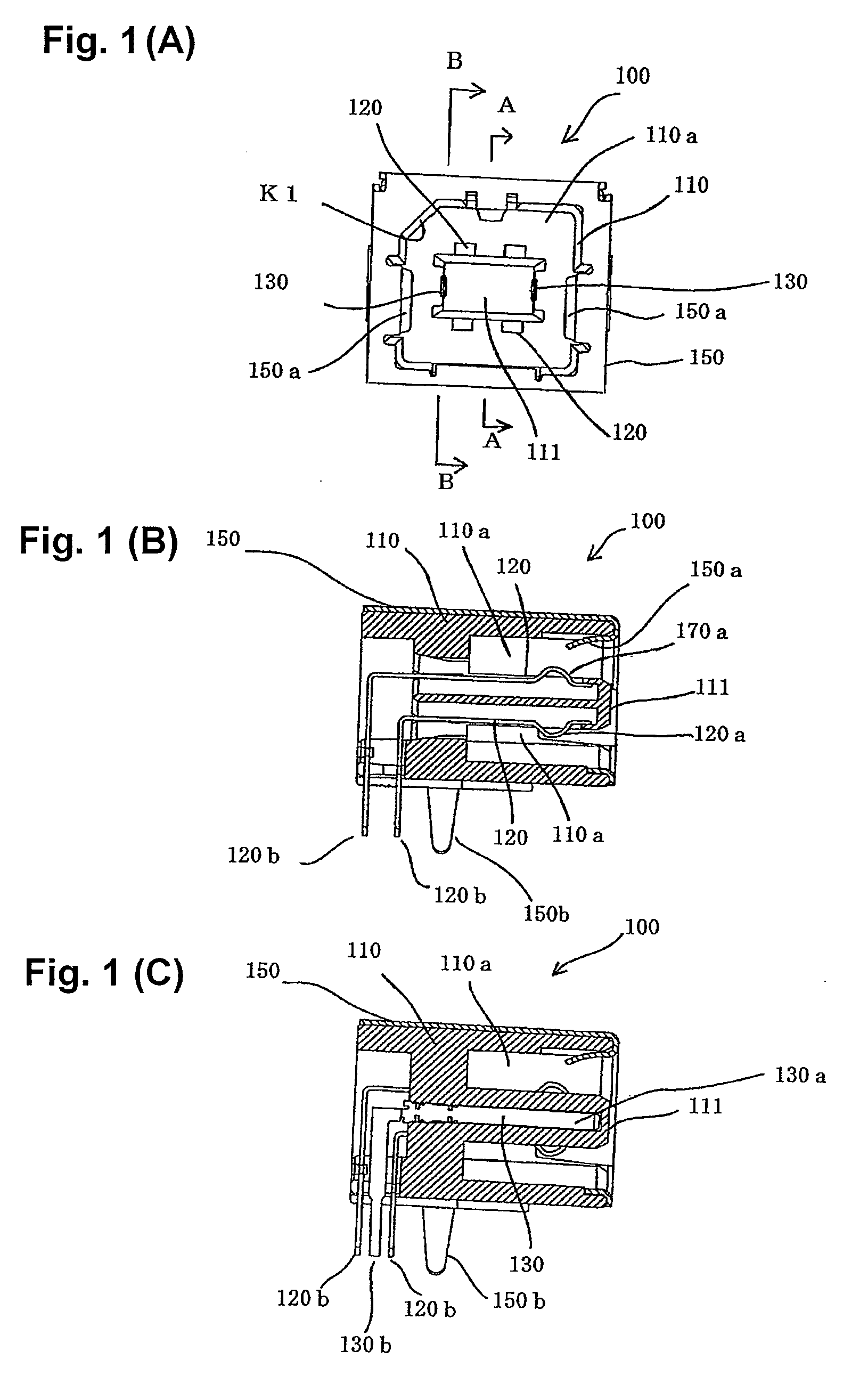
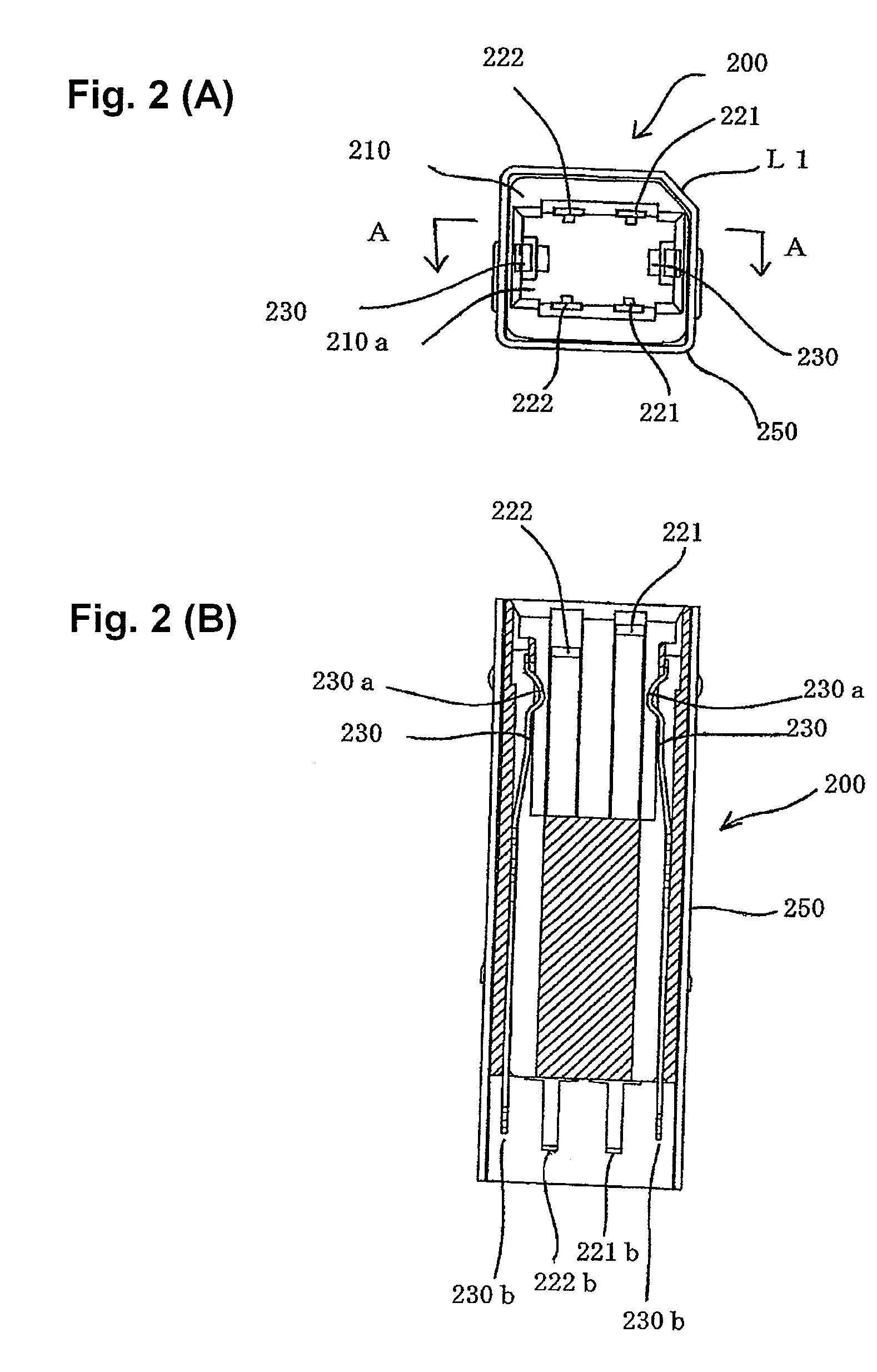
[0034] An electrical connector according to the invention comprises a receptacle 100 according to an embodiment of the present invention (FIGS. 1(A)-1(C)) capable of mating with either a plug 200 according to an embodiment of the present invention (FIGS. 2(A)-2(B)) or a USB-standard B-plug 300 (FIGS. 5(A) and 3(B)).

[0035] FIGS. 1(A)-1(C) show the receptacle 100 according to an embodiment of the present invention. As shown in FIG. 1(A), the receptacle 100 comprises an insulative housing 110 formed with substantially the same shape as an insulative housing of a USB-standard B-receptacle (FIGS. 5(A) and 3(B)). The insulative housing 110 has a recessed mating member 110a that opens into a substantially rectangular shape. A substantially cuboid protruding member 111 is formed in an approximate center of the recessed mating member 110a and protrudes toward a mating face thereof. Formed at an upper left corner of the recessed mating member 110a is a chamfered portion K1 that acts as a key...


PUM


Abstract

An electrical connector comprises a plug and a receptacle. The receptacle has an insulative housing with a protruding member having elastic contacts for signal and non-elastic contacts for power supply disposed thereon, wherein the non-elastic contacts are disposed on surfaces orthogonal to surfaces on which the elastic contacts are disposed. The plug has an insulative housing with an interior surface having elastic contacts for power supply and non-elastic contacts for signal disposed thereon, wherein the non-elastic contacts are disposed on surfaces orthogonal to surfaces on which the elastic contacts are disposed. A chamfered edge is provided on the plug and the receptacle such that either the plug or a conventional USB-standard B-plug can be received in the receptacle.

Description

FIELD OF THE INVENTION [0001] The present invention relates to an electrical connector for transmitting signals, and in particular relates to an electrical connector conforming to Universal Serial Bus (USB) or other standards. BACKGROUND OF THE INVENTION [0002] Several standards have been established for electrical connectors used to connect together an information-processing device having a host function (hereinafter referred to as a host device) as typified by a personal computer and an information-processing device not having a host function (hereinafter referred to simply as a peripheral device), such as the peripheral device of a personal computer. Of such standards, FIGS. 4(A)-5(B) show the configurations of conventional connectors based on the widely used USB standard (see FIGS. 8-9 of Unexamined Patent Application Publication JP2003-045582A). FIGS. 4(A)-4(B) show an example of a conventional USB-standard A-plug used for a connection on the host device (upstream) side. Moreov...

Claims


Application Information

Patent Timeline
Patent Type & Authority Applications(United States)
IPC IPC(8): H01R13/648
CPCH01R27/00H01R24/60H01R2107/00
Inventor IGARASHI, ISAOTODA, SHINSAKU
Owner TYCO ELECTRONICS JAPAN GK
Why Eureka
Try Eureka